Blog:
Solutions for Large Pointing Errors and Long Obstacle Avoidance Distances in Shuidi 2 Difference in Map Types and Type Analysis of Point 28
Difference in map types:
- V1 can build maps with more details, for a better positioning effect when the device is running, and it can be compatible with other models and maps of the Water series, but its mapping effect is not favorable for large and complex scenes.
- V2 is more convenient for mapping in large and complex scenes, and supports map continuation scanning. However, its maps are relatively rough and its positioning effect is poorer than that of V1. When high positioning is required and the scenes are not very complex, V1 is preferable for mapping.
Type analysis of Point 28: Point 28 is positioned relying on the matching degree between the laser data obtained in real time and the current map. Therefore, the physical environment needs to be relatively fixed to avoid random movement of movable objects such as people and pets as much as possible.
WARNING
It is recommended that there should be no obstacle, such as wall, within 70 cm around the location where precise parking is required (i.e. the center of the chassis).
Mapping and Correcting
Mapping
On the robot's web page, go to the
Map Managementpage and clickCreate Map. Then enterMap NameandFloor, and clickCreate Map.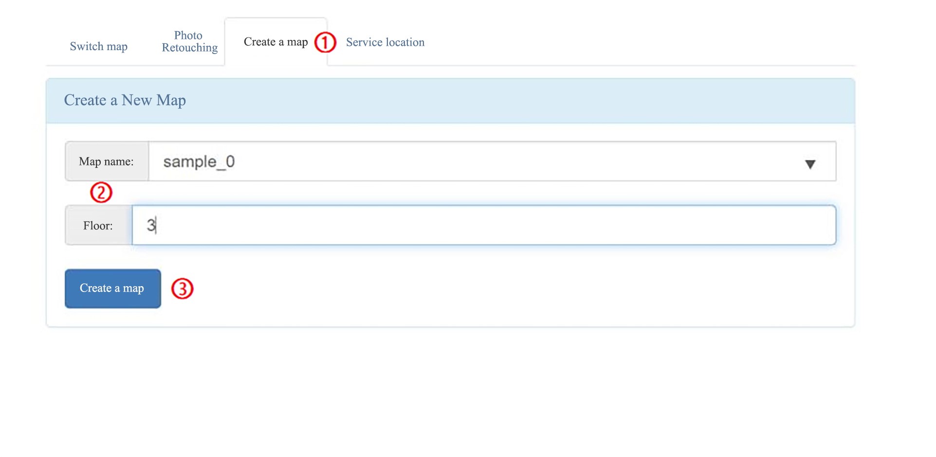
The page will jump to the Map Scanning Selection page, and the default choice is
V2 Mapping. ClickV1 Mappingon the left and selectSmall View.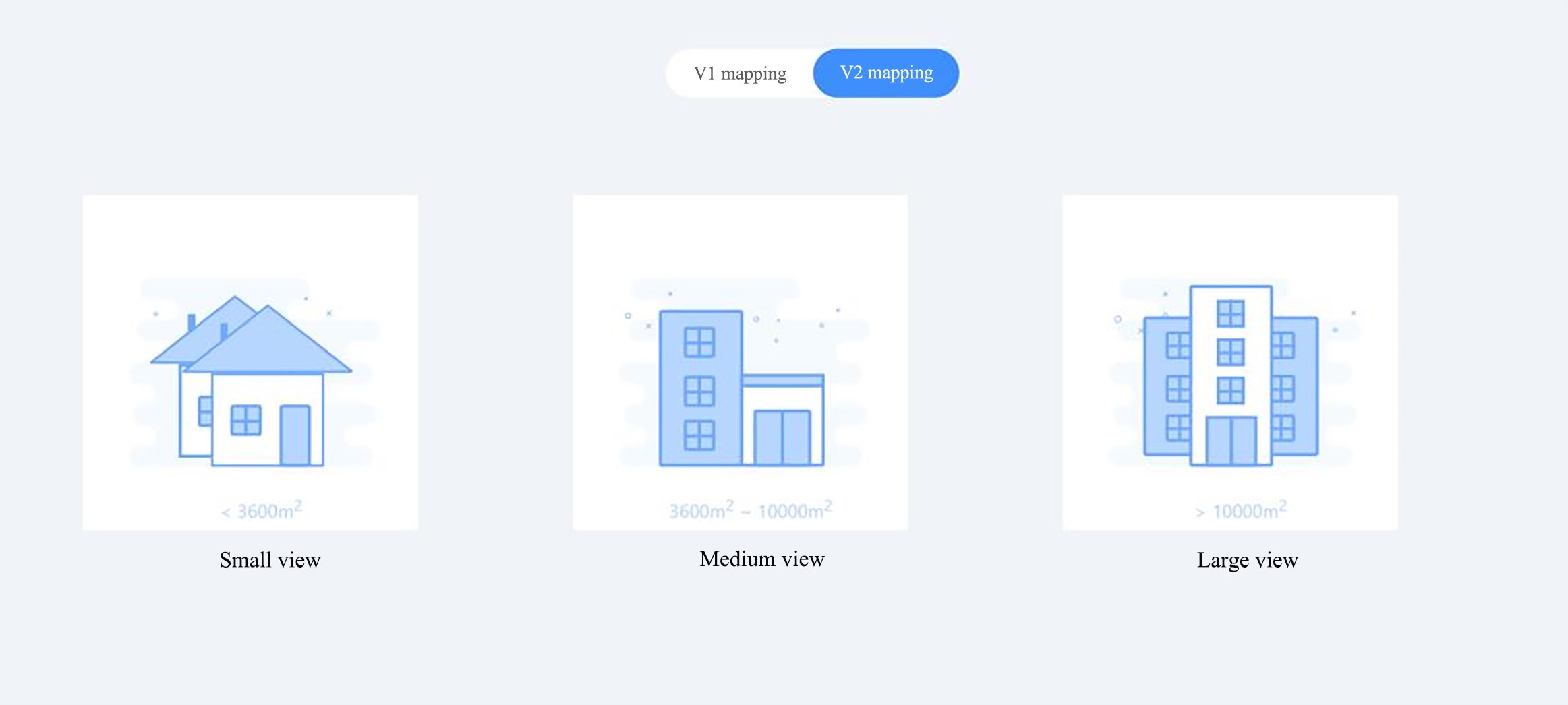
Then, the robot will switch to the scanning mode. The red color indicates the objects scanned by the lidar in real time, and the blue triangle indicates the robot itself, as shown in the figure below.
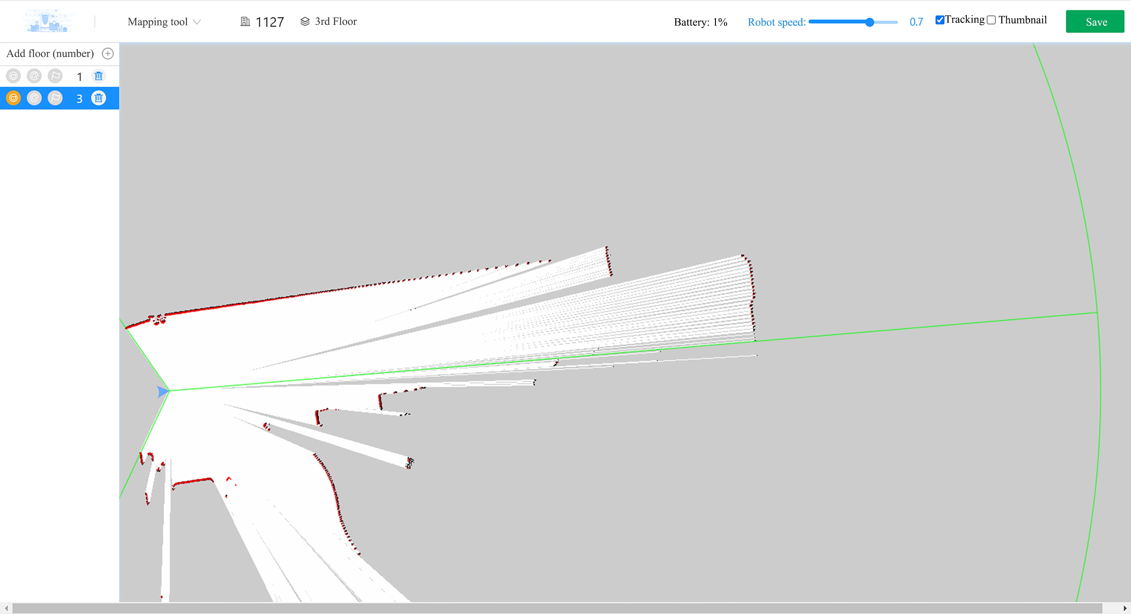
The use can press i (forward), j (left), k (backward), and l (right) keys on the keyboard to control the robot to complete mapping forward, which will not be elaborated here.
Correcting
After the map created in the previous step is loaded, if it is found that any object scanned by the lidar in real time does not match the map contour, you need to click Correct to make the scanned object completely match the map contour. Otherwise, the positioning will be inaccurate and the robot will not move as expected.
Press the Hard Emergency Stop button or click Soft Emergency Stop on the robot's web page, then manually push the robot to the target point, adjust the robot's attitude, release the emergency stop, click Mark Point, and select Add point at the current position.
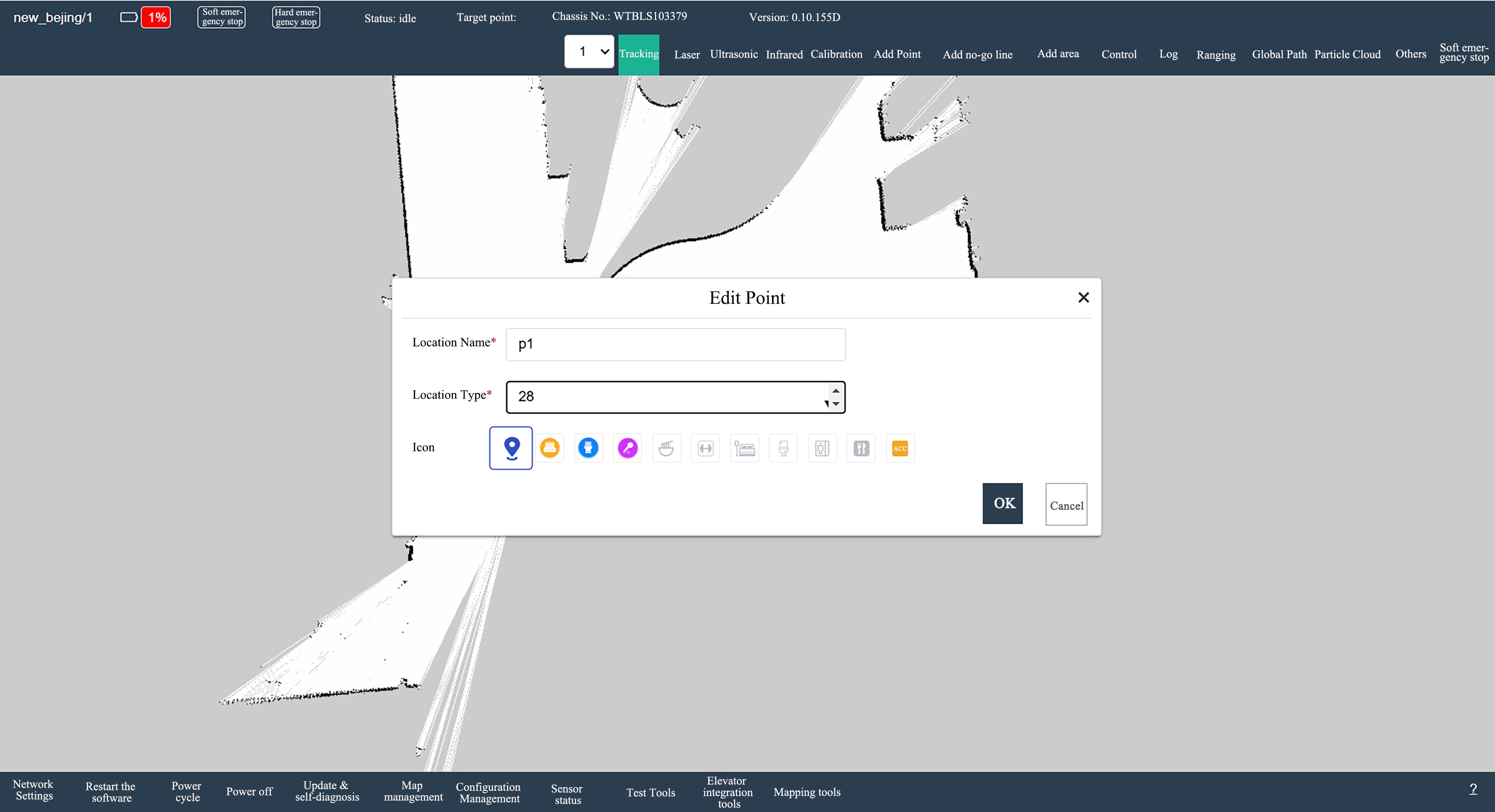
As shown in the figure above, set the name as p1 and the type as 28, and then click OK. Users can repeat this operation as described above to mark multiple points.
Configuration Management Settings
On the Configuration Management page of the robot’s web page, users can customize the configuration as needed. Refer to the following content for setting the configuration.
- Set
Safe Stop DistanceasDisable. - Set
Point Position Toleranceas minimum 0.05m. - Set
Point Angle Toleranceas minimum 0.05 rad.
Then click Save the Configuration in the lower left corner to save the settings.
Final Effects
- The reference value of the stop distance error is 2~5 cm.
- The reference value of angle deviation is 3°~5°.