Blog:
Troubleshooting for Compound Equipment Failure to Power On This article addresses the failure of compound equipment to power on, outlining troubleshooting steps for two core modules: the chassis and the robotic arm. It uses clear logic and accessible technical language to help engineers quickly identify issues and reduce downtime.
Chassis Fails to Power On
The chassis is the core of the compound equipment's mobility. If it fails to power on, troubleshooting should prioritize power supply and hardware faults, following these steps:
- Step 1: Verify Power Supply Status
Press and hold the power button. If the chassis shows no response, first check the battery level. If the battery is dead, connect a compatible charger. After fully charging, press and hold the power button again to attempt startup.
- Step 2: Determine if There is a Hardware Fault
If the chassis still fails to power on after charging (when pressing and holding the power button), it indicates an internal hardware fault (such as a damaged power module or motherboard failure). Personal repair carries high risks; you must contact technical support engineers directly for professional disassembly and inspection.
Robotic Arm Fails to Power On
The causes of a robotic arm failing to power on are more complex and require troubleshooting in the following order.
Step 1: Check the "Emergency Stop Button" and "Power Switch on the Housing"
The emergency stop button and the power switch on the housing are the safety barriers of the robotic arm. Accidental activation or failure to reset these components are easily overlooked issues.
| Inspection Object | Expected Status | Abnormal Handling Method |
|---|---|---|
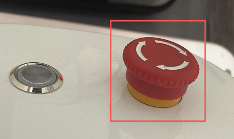
| Emergency Stop Button | Not pressed, fully popped up | If it is in the pressed state (see Figure a), rotate it to reset and ensure the button is fully popped up. |
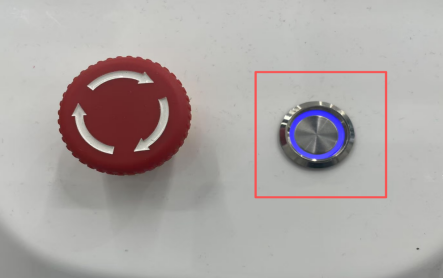
| Power Switch on the Housing | Pressed and latched, with the blue light at the button illuminated (see Figure b) | If it is not latched or the blue light is not on, press the switch again until it latches, and confirm the blue light is on normally. |
If the emergency stop button and the power switch on the housing are in the expected state but the problem persists, proceed with the following inspection.
Step 2: Judge System Health Status Through the Light Status of the Two Function Buttons at the End
The two function buttons (corresponding to blue light and green light respectively) at the end of the robotic arm serve as "system health signals." Their light status directly reflects the type of fault:
- Both function buttons are on + "beeping" sound:
If the blue light and green light are on, and there is a "beeping" sound inside the device, it indicates a "recoverable system alarm."
Solution: Use the teach pendant (see Figure c) to read the specific alarm code and clear the alarm according to the code prompt.
- Neither function button is on; check the controller power switch:
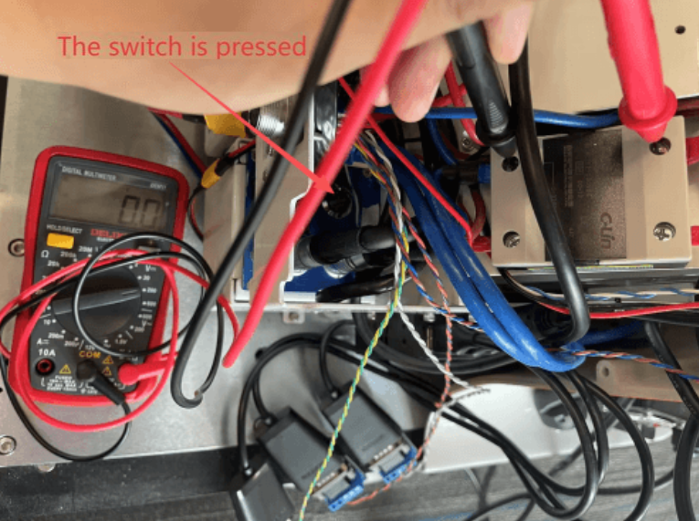
If neither of the two function buttons at the end is on, disassemble the housing on the back of the device (the area where the emergency stop button and the housing power switch are located) and check the status of the controller power switch:- Scenario 1: The controller power switch is pressed, but the LED blue light around the switch is not on. Use a multimeter to measure the voltage at the controller's power input terminal (see Figure d). If no voltage is detected, contact technical support engineers for handling.
- Scenario 2: The controller power switch is not pressed. Manually press the switch to the latched position and check if the function buttons at the end resume lighting. If they light up, the problem is resolved.
If the two function buttons at the end of the device are on normally and there is no "beeping" prompt sound, but the problem still exists, proceed with the following inspection.
Step 3: Output Voltage Inspection
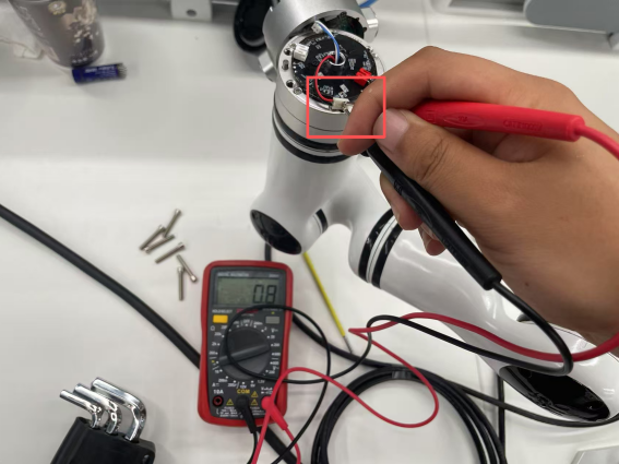
- Measure the voltage output of the yellow power connector:
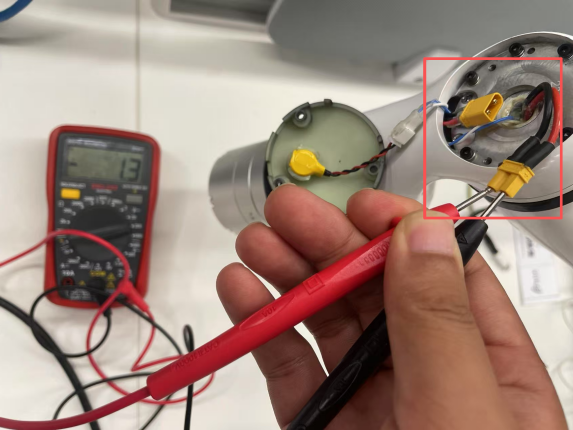
Remove the black end cover of the top joint of the robotic arm, locate the internal yellow power connector, and measure its voltage output (see Figure e).- If there is no voltage output: Contact technical support for handling.
- If there is voltage output: Proceed to the next inspection step.
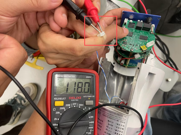
- Measure the voltage output at the power connector terminals on the circuit board Remove the end component of the robotic arm and measure the voltage output at the power connector terminals on the circuit board (see Figure f).
- If there is no voltage output: Contact technical support for handling.
- If there is voltage output: Proceed to the next inspection step.
Step 4: Troubleshoot the CAN Bus
- Disconnect the CAN bus connection terminal between the robotic arm controller and Joint 1.
- Measure the resistance value at both ends of the terminal (see Figure g. Under normal conditions, it should display "120Ω").
- If no resistance is measured (or the resistance value deviates significantly from 120Ω), contact technical support engineers for handling.
The above is the complete troubleshooting process for compound robots failing to power on. If you have any questions during actual operation, you can refer to the original text or consult technical support at any time.