Blog:
Debugging Methods for Force and Position Hybrid Control Parameters Technical Background
Hybrid force/position control: When the task of the robotic arm is to track trajectory motion in space, position control can be used. When the task of the robotic arm is to apply force and torque to the environment, force control can be used. When some directions of the force-controlled reference coordinate system are specified as force control, and the remaining directions are specified as position control, this control method is called hybrid force/position control.
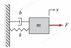
In the process of force control, the interaction between the end of the robotic arm and the contact environment is described as a "mass-spring-damper" system. When the spring, mass and damping parameters do not match the contact environment, unstable phenomena such as jumping will occur during the contact between the end of the robotic arm and the environment, and the corresponding force control tasks cannot be carried out normally. At this time, by setting appropriate inertia parameters M, damping parameters B and stiffness parameters K, the end of the robotic arm can operate stably after contacting contact environments with different stiffnesses.
According to the use scenarios of the robotic arm, common environments can be divided into three types: low-stiffness environment, medium-stiffness environment and high-stiffness environment:
- Low-stiffness environment: such as soft sofas, mattresses, etc. These objects have weak resistance to external forces and the robotic arm feels less reaction force when moving in them.
- Medium-stiffness environment: such as wooden tables, floors, etc. These objects have moderate resistance to external forces and the robotic arm feels moderate reaction force when moving in them.
- High-stiffness environment: such as metal structures, stones, etc. These objects have strong resistance to external forces and the robotic arm feels strong reaction force when moving in them.
Commissioning Analysis Method
The control system time-domain response performance metrics is used for analysis, which is defined as follows:
- Steady-state error ess: the difference between the expected and actual values of the output response. It is used to the tracking accuracy of the reaction system. The smaller the steady-state error, the higher the control accuracy. Steady-state errors are usually required to be within 5% of the expected value, and 5% is called the steady-state allowable error band ∆.
- Rise time tr: the time from zero to the first steady-state value. It is used to measure the system response speed. The shorter the rise time, the faster the system response.
- Peak time tp: the time from zero to peak. The rapidity of the reaction system response, the shorter the peak time, the faster the response speed.
- Maximum overshoot Mp: The ratio of the difference between the maximum peak value and the steady-state value of the response curve to the steady-state value. It is used to measure the stability and damping degree of the system. The larger the overshoot, the more violent the system oscillation and the worse the stability.
- Adjustment time ts: The time corresponding to the response curve entering the steady-state value allowable error band ∆. It is used to measure the rapidity and stability of the comprehensive reaction system, the shorter the adjustment time, the faster the system will return to steady state.
- Reach error tm: There is a position difference between the end of the robotic arm and the contact environment. The end of the robotic arm needs to run for a period of time tm before it can contact the environment, so the time tm needs to be subtracted in performance analysis.
Brief Introduction to Commissioning Method
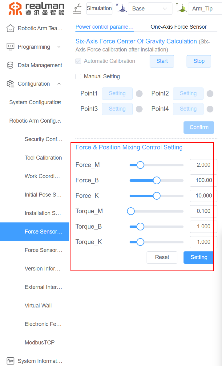
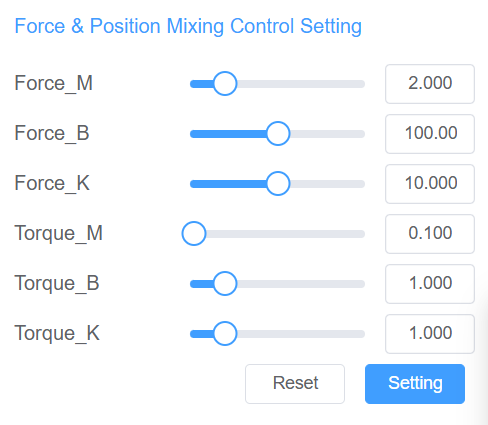
Hybrid force/position control parameters are divided into force direction control parameters and torque direction control parameters.
- Force direction control parameters: The force direction refers to the three directions of X, Y and Z of the force-controlled reference coordinate system, that is, the three translation directions. The force direction control parameters include three parameters: force direction inertia, force direction damp and force direction stiffness.
- Torque direction control parameters: The torque direction refers to the three directions of Rx, Ry and Rz of the force-controlled reference coordinate system, that is, the three rotation directions. The torque direction control parameters include three parameters: torque direction inertia, torque direction damp and torque direction stiffness.
The stiffness, inertia and damping parameters of the three force directions and three torque directions of the force-controlled reference coordinate system can be set separately on the teach pendant.
TIP
The default hybrid force/position control parameters of the RealMan robotic arm are suitable for healthcare robotic arms (medium-stiffness environment) and can be used as reference values for commissioning.
Hybrid Force/Position Control Parameter Commissioning Objective
Set appropriate hybrid force/position control parameters (inertia parameter M, damping parameter B and stiffness parameter K) so that when the end of the robotic arm contacts the contact environment, the force data change curve during the force control process meets the requirements of "fast, accurate and stable", that is, the control system has fast response speed, small overshoot, few oscillations and small steady-state error.
Reference steps for hybrid force/position control parameter commissioning:
Click Reset to reset the hybrid force/position control parameters to default values. The design task generates a force data change curve for the force control process, and adjusts the hybrid force/position control parameters according to the surface until the hybrid force/position control parameter commissioning objective is met.
Hybrid force/position control parameter commissioning method:
- When the response of the control system lags, you may try to reduce the inertia parameter M.
- When the end of the robotic arm has a large rebound (large overshoot) when it contacts the contact environment, you may try to reduce the stiffness parameter K.
- When the control system oscillates many times and it is difficult for the system to converge, you may try to increase the damping parameter B.
WARNING
Do not make large adjustments to multiple hybrid force/position control parameters at one time, but debug each parameter one by one, and adjust them in a small range each time, and then conduct sufficient performance tests. If multiple parameters such as inertia parameter M, stiffness parameter K and damping parameter B are adjusted significantly at one time, the robot arm movement may be completely out of control or have very poor performance. It is difficult to judge what role each parameter adjustment has played.
Examples for hybrid force/position control parameter commissioning:
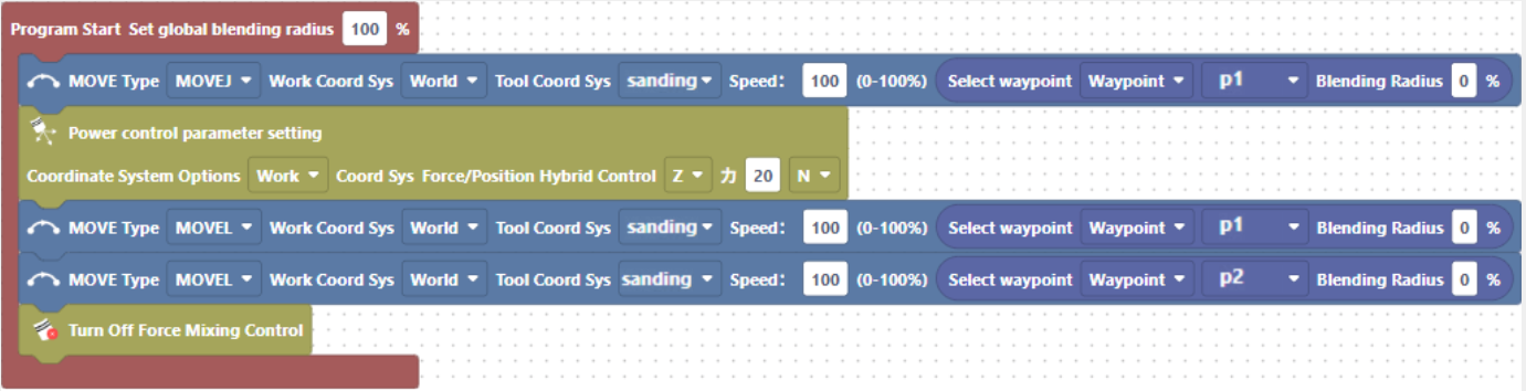
Design a task for a robotic arm to perform force control only in the Z direction of the force control reference coordinate system (no movement in other directions), run the task and collect data to generate a force data change curve during the force control process, and use the control system time-domain response performance metrics for analysis.
Video won't load? Click to view
By collecting task scripts, task operation status and force data during force control process, the change curve is sorted and analyzed as follows: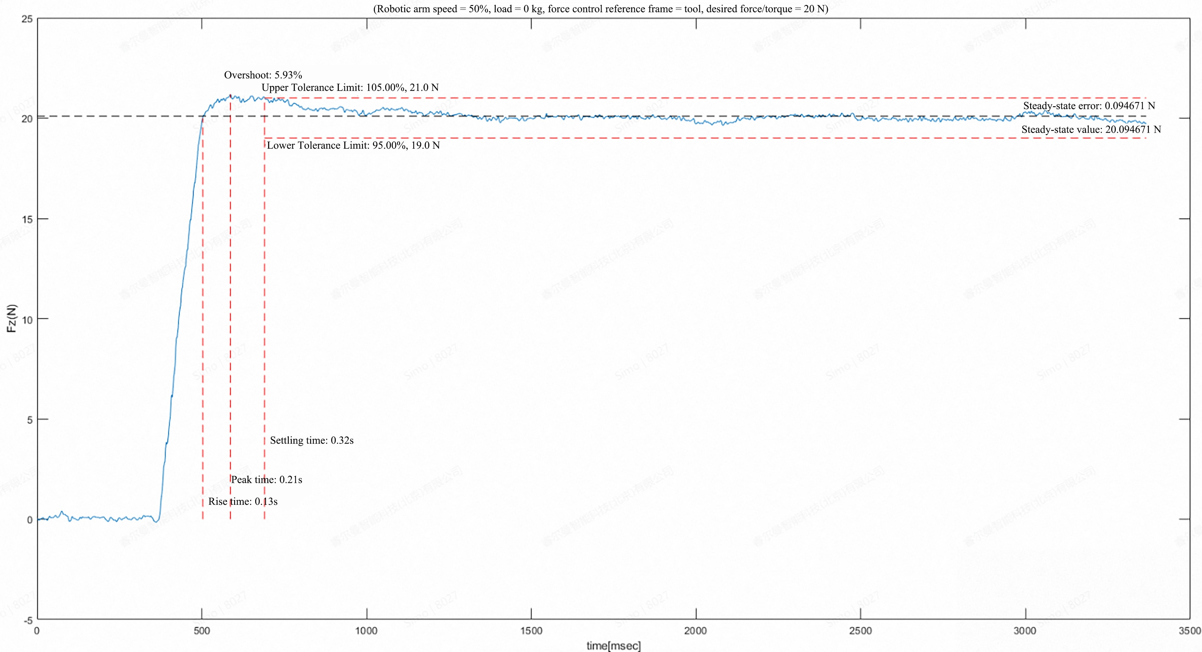
References
Classic literature: Ott C, Mukherjee R, Nakamura Y. Unified Impedance and Admittance Control[C]// IEEE International Conference on Robotics & Automation. IEEE, 2010:554-561.