Blog:
User Manual for Teleoperation Dedicated Solver API Core Inverse Kinematics API Analysis
Inverse Kinematics Initialization rm_algo_ik_remote_init
This dedicated interface for teleoperation / singularity avoidance scenarios serves to establish the foundation for subsequent inverse kinematics calculations.
TIP
Ensure that the Cartesian pose difference components issued by the user, when divided by the command cycle, do not result in a velocity exceeding the maximum speed limit threshold configured in the teach pendant's safety settings.
Inverse Kinematics Core Function rm_algo_ik_remote
The core execution function for inverse kinematics calculation, responsible for solving continuous Cartesian poses.
TIP
This dedicated inverse kinematics solver is only applicable for solving continuous Cartesian poses. It cannot be used for point-to-point motion functions like movj_p.
Recommended workflow: First verify the accuracy and motion rationality of the issued poses in a simulation environment. Only after confirming no anomalies, switch to real-world mode to avoid risks during physical robot debugging.
WARNING
To ensure the normal operation of the robotic arm, please keep the elbow joint (joint 4 for a 7-axis robotic arm / joint 3 for a 6-axis robotic arm) from being fully extended (i.e., at a joint angle of 0°) during operation. When the joint continues to move beyond its boundary after full extension, due to the characteristics of boundary singularity, unpredictable phenomena such as robotic arm oscillation and difficulties in returning may occur. It is recommended to set a non-zero soft limit for the elbow joint by using the provided limit-setting interface or configuring joint soft limits in the safety settings page of the teach pendant. Specific limit values can be determined in a simulation environment before being applied to the actual system.
This function already includes built-in soft limit protection mechanisms for all joints, but it is still advisable to operate within the normal motion range and avoid reaching the soft limit boundaries. If a joint has already reached its soft limit but needs to move beyond the limit to achieve a target pose, it may easily lead to robotic arm oscillation or other uncertain motion states due to conflicting motion constraints.
Pose Tracking Weight Configuration rm_algo_set_error_weight
Used to customize the tracking weight for each component (x, y, z, ax, ay, az) of the end-effector pose.
The weight value directly correlates with the solving accuracy in the corresponding Cartesian direction—a higher weight results in higher pose tracking accuracy in that direction.
If this interface is not actively called, the system defaults all component tracking weights to 1 (this default is suitable for most scenarios and requires no additional adjustment). Parameter range: 0.01~1.0.
Joint Speed Limiting Function rm_algo_set_dq_weight
When a specific joint's motion speed is found to be too fast or too aggressive, use this interface to adjust the speed limiting weight for that joint. In the default state, all joint speed limiting weights are 1.0 (no additional speed limiting). Parameter range: 0~1.0.
TIP
Speed limiting settings may cause slight tracking errors in the end-effector pose. A balance must be found between motion smoothness and tracking accuracy.
Custom Joint Limit rm_algo_set_joint_limit_angle
A limit interface designed for requirements such as "preventing straightening" or "preventing elbow inversion" during robot arm motion. It allows flexible setting of joint motion ranges based on actual scenarios. Core configuration rules:
6-axis robot arm: The joint to prevent straightening is the elbow joint (Joint 3).
7-axis robot arm: The joint to prevent straightening is the elbow joint (Joint 4). Simultaneously, limit setting for Joint 3 is supported (because 7-axis arms have null-space motion, the combined action of Joint 3 and Joint 4 is needed to achieve the elbow restriction effect).
WARNING
- The initial joint angle must not exceed the set limit range.
- If the 7-axis elbow tracking function is enabled, be mindful of potential limit conflicts.
7-axis Exclusive - Elbow Control Enable rm_algo_enable_q3_tracker
Supports elbow control functionality exclusively for 7-axis redundant robot arms. Its core principle is to indirectly control elbow posture by tracking the motion state of Joint 3.
7-axis Joint 3 Tracking Target Angle rm_algo_set_7dof_q3_track_angle
Used to set the tracking target angle for Joint 3 of a 7-axis robot arm. Clarification: This interface does not command Joint 3 to precisely reach the target angle instantly. Instead, it provides motion guidance for Joint 3 through null-space motion—if motion time tends to infinity, Joint 3 will gradually converge to the target angle.
TIP
The set target angle should avoid the configured joint limit range to prevent motion conflicts.
Elbow Tracking Level rm_algo_set_q3_tracker_velocity_level
Specifically adjusts the response speed for elbow tracking in 7-axis robot arms. Parameter range: 0~1.0.
- A larger value results in more aggressive null-space motion response, making Joint 3 converge to the target angle faster.
- Adjust flexibly according to actual motion scenarios to avoid sudden elbow posture changes due to excessively fast tracking speed.
Practical Example
Taking the RM75B model as an example in the application scenario of a humanoid right arm, combining limit settings with the elbow tracking function adds constraints to the inverse kinematics solution, achieving more natural anthropomorphic postures.
Problem Scenario
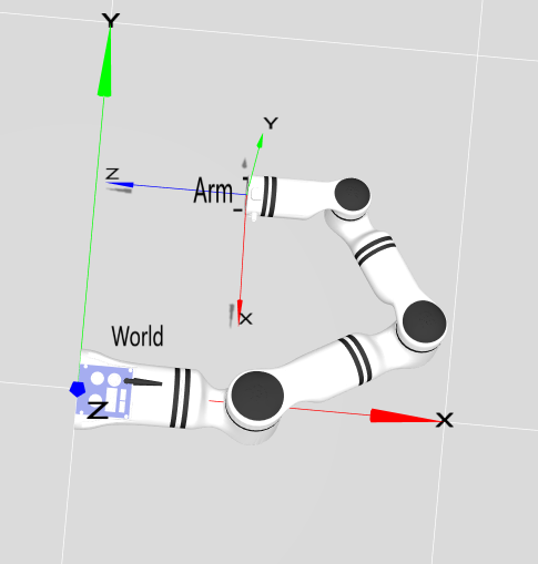
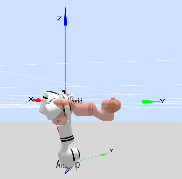
During robot arm motion, an inverted elbow configuration as shown in Figure 2 can easily occur. This posture not only deviates from human motion habits but may also cause the robot arm to collide with the surrounding environment, affecting motion safety.
Solution
Add limits to the elbow joint (Joint 4)
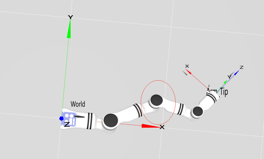
For the inversion problem in Figure 2 (Joint 4 angle is -40 degrees), the minimum limit for Joint 4 can be set to 3 degrees. By adding this limit constraint, the joint will not move towards angles less than 3 degrees during motion, thus keeping the elbow always facing outward and avoiding inversion (the principle is the same for elbow restriction in our company's six-axis arms), as shown in Figure 3:
Add limits to the elbow joint (Joint 4) + Add constraints to Joint 3
As a redundant configuration device with null-space motion characteristics, a seven-axis robot arm cannot fully solve the elbow inversion problem with single-joint limits. It requires setting limits for Joint 4 while also adding constraints for Joint 3.
Rotation of Joint 3 causes elbow inversion:
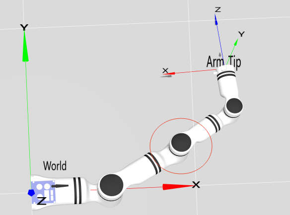
As shown in Figure 4, even if other joints maintain optimal configurations, abnormal rotation of Joint 3 can still lead to elbow inversion.
Joint 4 constraint + Joint 3 constraint
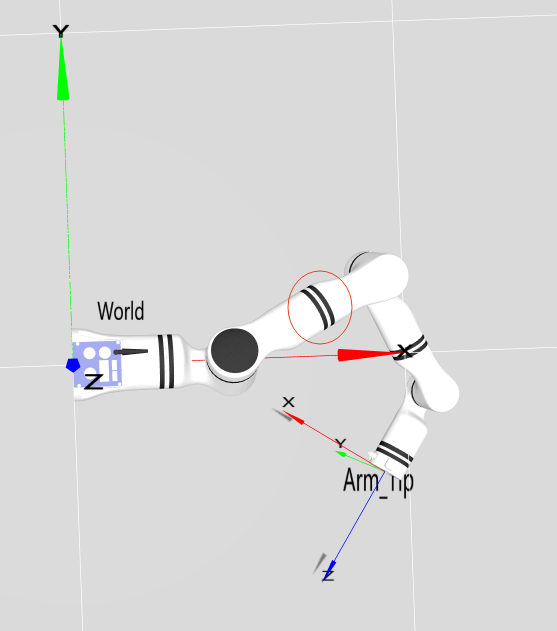
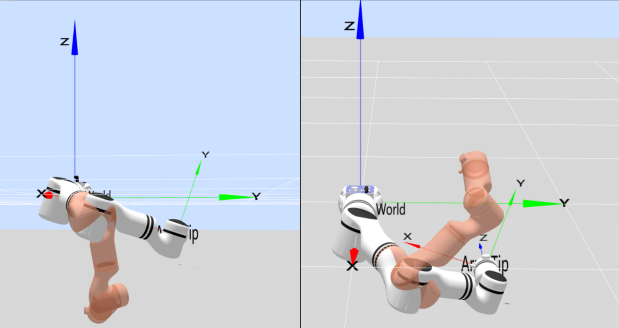
For a seven-axis arm, elbow restriction relies not only on Joint 4 constraints but also on Joint 3 constraints. As shown in the red virtual models in Figure 5, the positions of Joint 3 are -60 degrees and 60 degrees respectively. Therefore, by adding maximum and minimum limits of 60 degrees and -60 degrees to Joint 3, its position can be constrained, preventing the elbow inversion problem caused by Joint 3 rotation as seen in Figure 4.
Elbow Tracking Function
For seven-axis arms, the elbow tracking function can also be used, which is indirectly implemented by controlling Joint 3. Taking the left image of Figure 5 as an example, if movement towards a normal configuration is desired, the target should be the red virtual model in Figure 6. The Joint 3 angle of the current red virtual model is 16 degrees. Therefore, the seven-axis elbow tracking function can be enabled with the Joint 3 tracking angle set to 16 degrees. During motion, the arm will perform null-space motion and gradually move towards this normal configuration.
Summary and Usage Recommendations
Six-axis robot arm: The elbow restriction scheme is achieved solely by limiting the elbow joint (Joint 3).
Seven-axis robot arm: The elbow restriction scheme requires a flexible and skillful combination of limit constraints for Joint 3 and Joint 4, along with the elbow tracking function.
Through the flexible application of this set of inverse kinematics API interfaces, stable control of the robot arm in scenarios such as teleoperation and singularity avoidance can be easily achieved. Combined with anthropomorphic limit and tracking strategies, the robot arm's motion becomes more ergonomic, adapting to more high-precision application scenarios.