Blog:
The Impact of Robotic Arm Zero Position and Its Settings I. What Is the Zero Position of a Robotic Arm?
The zero position of a robotic arm refers to the reference initial position for the joints and motion axes of the robotic arm. This is a standard position of the robotic arm pre-defined before any operation, and all movements and positions are calculated based on this zero position. Therefore, it is very important to ensure that the robotic arm is in the zero position before any operation.
The zero position is generally set when a robotic arm is delivered from the shop, and there is no need to reset the zero position under normal circumstances.
The zero position must be reset in the following situations:
- The driver gives an alarm as the number of encoder disc turns is lost after the encoder disc battery of the robotic arm is replaced. In this case, zero calibration is required.
- The motor, reducer, or mechanical transmission parts are removed or replaced.
- The robotic arm is influenced by external shock or vibration during operation, resulting in zero shift.
II. Impact of Zero Position Loss on Robotic Arms
Zero position loss of robotic arm will have a variety of serious effects, as follows:
- Reduced positioning accuracy: The robotic arm cannot accurately locate the predetermined position, resulting in errors. For example, on an assembly line, zero position loss may result in that parts cannot be accurately installed, affecting product quality.
- Reduced repeatability: The position of the same task may be different every time, affecting production consistency. For example, for spot welding, the position of each weld point may be different, resulting in unstable welding quality.
- Path offset: The preset motion path will shift due to zero position loss, causing the robotic arm to collide with other devices or obstacles. On complex production lines, this might cause serious equipment damage or production stagnation.
- Process flow interruption: Path planning errors will cause the robotic arm to fail to complete the predetermined operation steps, thereby interrupting the process flow. For example, in spray coating, an incorrect path will cause uneven spraying, and rework is needed.
- Increased wear of the robotic arm: The robotic arm may collide with other devices or workpieces due to misoperation or an incorrect path, resulting in damage to the robotic arm or other devices. For example, The robotic arm may hit a shelf or other mechanical devices when it deviates from the track during handling heavy objects.
- Potential safety hazards: Malfunction of the robotic arm may cause harm to surrounding operators, posing a safety hazard. For example, in a human-machine collaborative work environment, zero position loss may cause the robotic arm to move unexpectedly, endangering the safety of the operators.
III. What Situations May Cause Zero Position Loss?
Zero position loss of a robotic arm can be caused by a variety of behaviors or factors. Some common causes are listed below:
- Mechanical shock: The robotic arm is influenced by external shock or vibration during operation, which might result in zero shift.
- Sensor fault: Position sensors (such as encoders and limit switches) are faulty or aged and cannot accurately measure the position of the robotic arm.
- Joint and bearing wear: The joints and bearings of the robotic arm will be worn after long-term use, resulting in a decrease in motion accuracy and affecting the zero position.
- Power supply fluctuation: Voltage fluctuation or instantaneous power outage may cause the control system to restart and lose the zero information.
- Software setting error: Setting errors or program errors in the control software may cause the zero position information of the robotic arm to be lost or overwritten.
IV. Method for Setting the Zero Pose
When zero pose loss occurs, it is necessary to reset the zero pose of the robotic arm in time so as not to affect its subsequent use. Taking RM65-B as an example, the following content shows the steps to reset the zero pose:
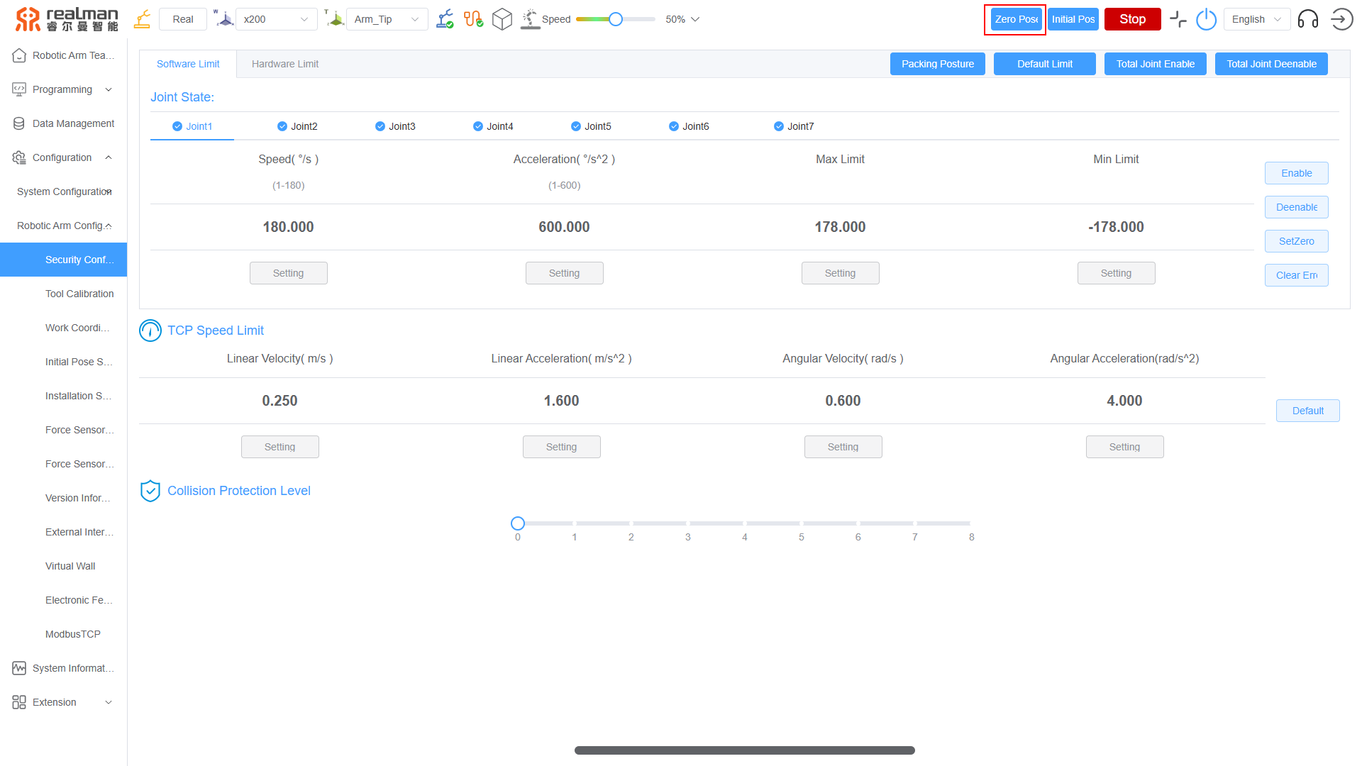
- Log in to the Robotic Arm Teaching, click
Zero Posein the upper right corner, and let the robotic arm return to zero.
- After the robotic arm returns to the zero pose, observe whether the grooves of joints are aligned. If not, it means that zero pose loss occurs. You need to hold down the green button to manually align the grooves, or use stepping to align the grooves.

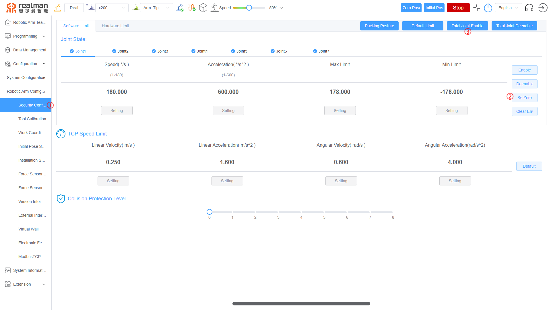
- After the grooves are aligned, click
Security Configurationon the left side of the Robotic Arm Teaching, and clickSetZerofor each joint in sequence. Then, you can hear the robotic arm make a "beep beep beep" sound. Finally, click theTotal Joint Enablebutton, and the green light of the robotic arm controller starts to flash.
V. Method for Checking the Zero Pose
After the zero pose is set, manually drag the robotic arm to any other position, click the Zero Pose in the upper right corner of the Robotic Arm Teaching, and the robotic arm returns to the zero pose. Check whether the grooves of joints of the robotic arm are aligned. If the grooves are aligned, the zero pose is set successfully.
VI. Preventive Measures
- Periodic calibration: A periodic calibration plan should be scheduled according to the frequency of use and working environment of the robotic arm. Usually, calibration should be performed once a month or quarter.
- Sensor maintenance: The position sensors (such as encoders and limit switches) should be checked for their working status regularly to ensure their normal operation. In addition, the sensors should be cleaned regularly to prevent dust and dirt from affecting their performance, and should be calibrated as necessary.
- Using a voltage stabilizer: A voltage stabilizer should be installed to ensure stable power supply voltage and avoid voltage fluctuations affecting the control system of the robotic arm.
- Uninterruptible power supply (UPS): An UPS should be provided to prevent instantaneous power outage or power fluctuation from causing the control system to restart.