Application Integration Case:
Autonomous Polishing Workstation I. Project Overview
1.1 Project Background and Objectives
With the rapid development of industrial automation, there is a growing demand for high-precision and efficient manufacturing processes. Especially in metal processing and manufacturing, polishing is a key step to improve product quality and appearance. Traditional manual polishing methods has problems such as low efficiency, high cost, unstable quality, and hazards to workers' health. To solve these problems, we proposed Autonomous Polishing Workstation v1.0, to achieve an automated and intelligent polishing operation by integrating up-to-date robot technologies, intelligent control algorithms, and machine vision systems.
Project objectives:
Automated polishing: To realize a fully automated polishing operation with lower manual intervention but higher production efficiency and consistency.
Quality improvement: To improve the polishing quality and reduce the product defect rate by accurately controlling the polishing force and path.
Cost saving: To reduce the labor cost and material consumption, and improve the economic benefits of enterprises.
Health and safety: To reduce the risk of workers being exposed to harmful dust and noise, and improve the working environment.
Flexibility and adaptability: To enable the workstation to adapt to workpieces of different shapes and materials, for higher flexibility of production lines.
Environmental friendliness: To reduce energy consumption and waste generation by optimizing the polishing process, to achieve green manufacturing.
Technological leadership: To maintain technological leadership and enhance market competitiveness by introducing force-position hybrid control and attitude hybrid control technologies.
By achieving these objectives, Autonomous Polishing Workstation v1.0 will bring revolutionary production methods to enterprises, and promote the manufacturing industry to develop in a more efficient and intelligent direction.
1.2 Core Functions
The main purpose of Autonomous Polishing Workstation v1.0 is to achieve automated polishing in the manufacturing process, improve production efficiency and product quality. Its core functions include:
Automated polishing:
Quickly setting the polishing trajectory: The workstation can automatically identify the trajectory and curvature characteristics of the workpiece to be ground by pre-setting the starting point and end point of the polishing trajectory.
Continuous operation: It can continuously grind multiple workpieces without human intervention.
Precise positioning:
- High-precision sensors: High-precision force sensors are used to achieve precise positioning of workpieces.
Force-position hybrid control:
Force control: The polishing force is monitored in real time by force sensors to ensure uniform and appropriate polishing.
Position control: The position of the robot's end effector is controlled precisely to achieve a precise polishing trajectory.
Attitude hybrid control:
Multi-degree-of-freedom adjustment: The robot has multiple degrees of freedom (DoF) and can adjust its attitude according to the shape and position of the workpiece.
Adaptability to complex surfaces: It can adapt to the polishing needs of complex surfaces and achieve all-round polishing with no neglected corners.
Modular programming:
Easy to program: Modular programming makes it easy to write and modify the program.
Quick deployment: The modular design makes it faster and more flexible to deploy new tasks and adjust.
Safety monitoring:
Emergency stop: When an abnormal situation is detected, the polishing operation can be stopped immediately by pressing a button, to ensure the safety of personnel and equipment.
Status monitoring: The equipment status, including temperature, wear and energy consumption, is monitored in real time through the HMI to prevent failures and accidents.
These core functions form the technical foundation of the autonomous polishing workstation, enabling it to provide efficient and precise polishing services in a variety of industrial applications.
1.3 Technical Highlights
Force-position hybrid control technology:
This technology combines force control and position control, allowing the robot to achieve precise control of both force and position during polishing, to improve polishing accuracy and efficiency.Attitude hybrid control:
Robot attitude adjustment enables the workstation to adapt to workpiece surfaces of different shapes and angles, achieving all-round polishing with no neglected corners.Modular programming:
Modular programming makes the program easy to write, modify, and maintain, while being able to quickly adapt to different polishing needs and tasks.
These technical highlights represent the advantages of Autonomous Polishing Workstation v1.0 in automation, precision, and flexibility as a workstation designed to improve polishing efficiency and quality in industrial manufacturing processes while reducing the labor cost and operational risks. The application of these technologies enables the workstation to better adapt to changing production environments and meet the needs of different customers.
1.4 Update Log
| Update Date | Update Content | Version No. |
|---|---|---|
| December 19, 2024 | Initial version release. | v1.0.0 |
II. Hardware Environment
This project can be realized only by using a six-dimensional force robotic arm. Please make sure that your robotic arm is six-dimensional force type.
2.1 Basic Hardware Functions
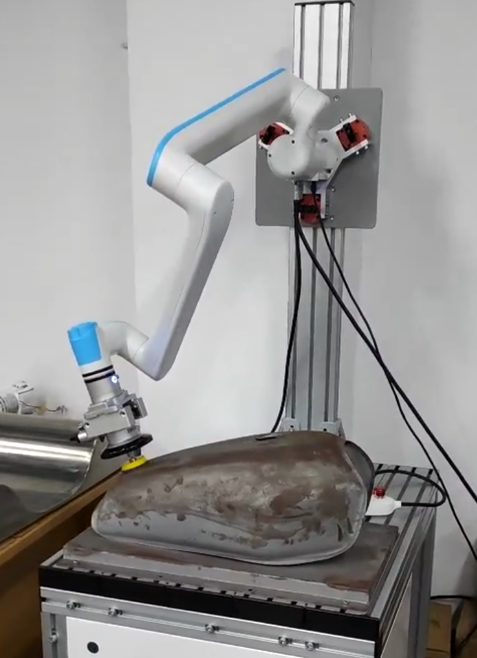
- End polishing tool: This tool is used to polish workpieces such as those with curved surfaces, and is controlled by signals through the control panel at the end of the robotic arm. Its attitude is autonomously adjusted by the force sensor at the end of the robotic arm that senses the surface features.
- RealMan robotic arm: The movement of its motors is controlled by the control signal of the RM controller, to finally obtain the overall movement effect of the robotic arm.
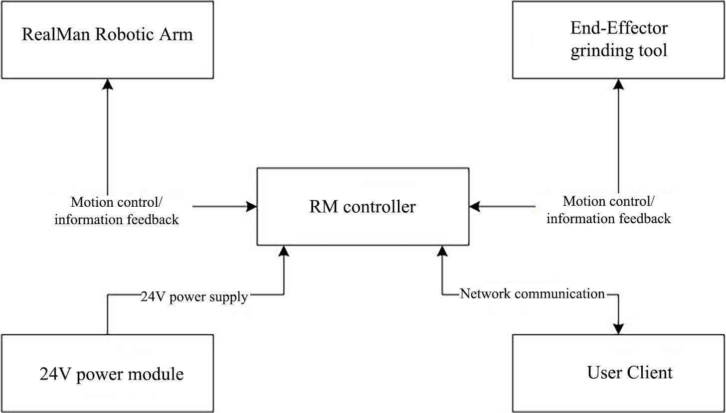
- 24V power module: This module supplies power for the entire control system.
- RM controller: It is connected by cable through the network interface, and controls the robotic arm to perform corresponding actions through the HMI, C++ program interface, Python program interface, etc. In addition, it also obtains the status information of the robotic arm's different modules to monitor the status of the robotic arm.
2.2 Hardware Communication Framework
III. Software Environment
- Control mode of HMI
- System version: All
- System architecture: X86/ARM64
- Control mode of program interface
- Interface tool: Python/C++
- Required version: Python 3.9 or later
IV. Preparation Stage
Access the RM controller with an external PC.
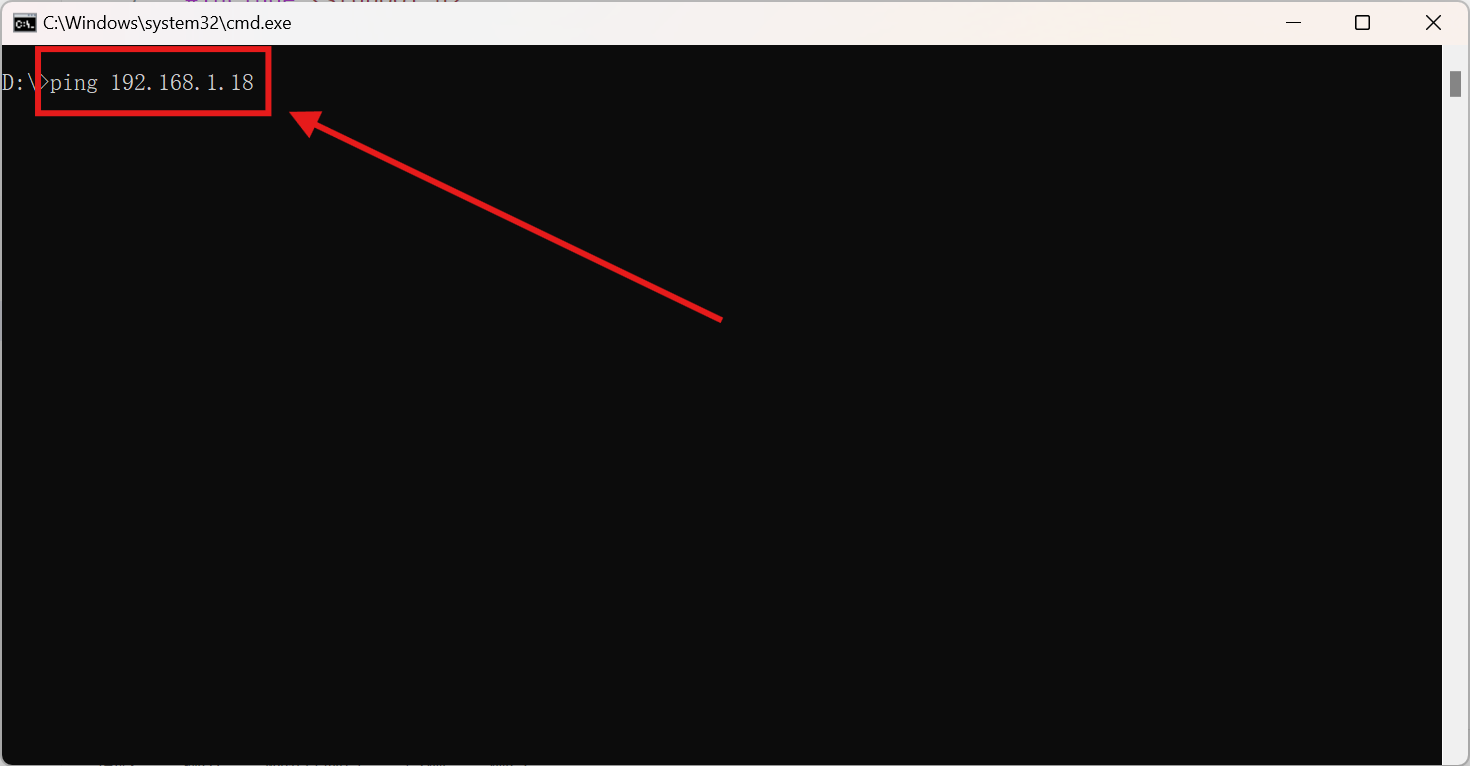
- Configure the
IPaddress of the external PC as needed. PING the IP address of the robotic armwith the commandping 192.168.xxx.xxx, to test whether it is successfully connected to the robotic arm (The defaultIP address of the robotic armis192.168.1.18).- If the robotic arm is to be controlled by the HMI, enter the IP address of the robotic arm's controller in the browser’s search box. If the robotic arm is to be controlled by an interface, write corresponding Python/C++ source code.
4.1 Configuring User IP
- Connecting the HMI
The robotic arm can be connected through the network interface or WiFi. For specific connection methods, refer to Teach pendant connection.
Connection test
Press Win+R to open the running window, enter the cmd command and press Enter to open the terminal.
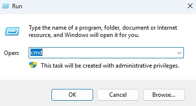
Ping the default IP address of the robotic arm to test whether the robotic arm and the PC can access each other successfully.
4.2 Calibrating Six-dimensional Force
Since the six-dimensional force sensor is used to sense the surrounding environment data in this case, it is inevitable to calibrate the six-dimensional force sensor at the end of the robotic arm to avoid the influence of the end polishing tool on the perception of the six-dimensional force sensor. The specific calibration process is as follows.
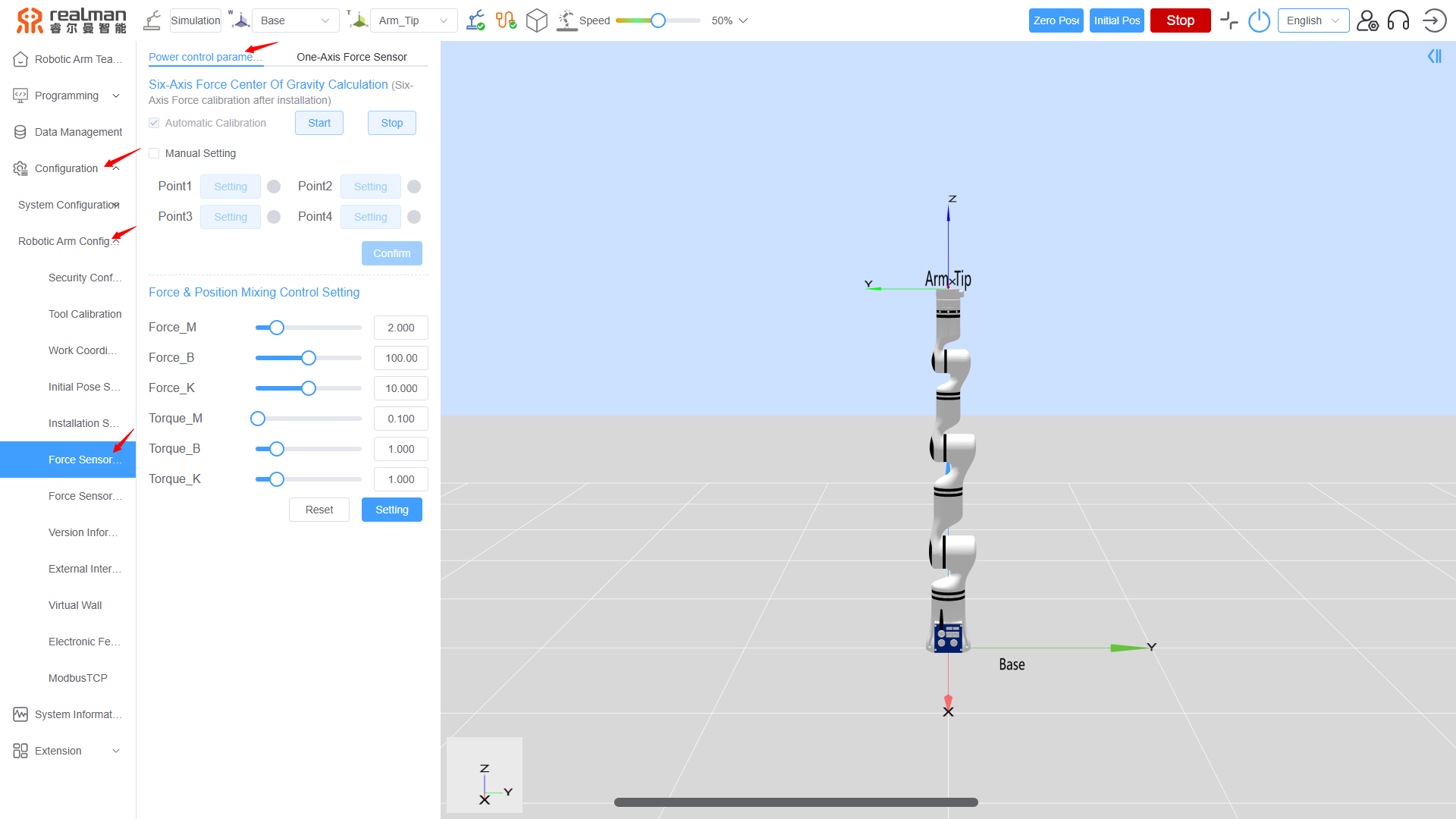
On the home page of the HMI, and click Configuration > Robotic Arm Configuration > Force Sensor Configuration, to go to the Force Sensor Configuration page.
For the calibration operation, refer to
Six-Axis force calibrationin Force Sensor Calibration.
TIP
- To prevent the robotic arm from colliding during calibration, the robotic arm or the workstation should be moved to a relatively open place as much as possible.
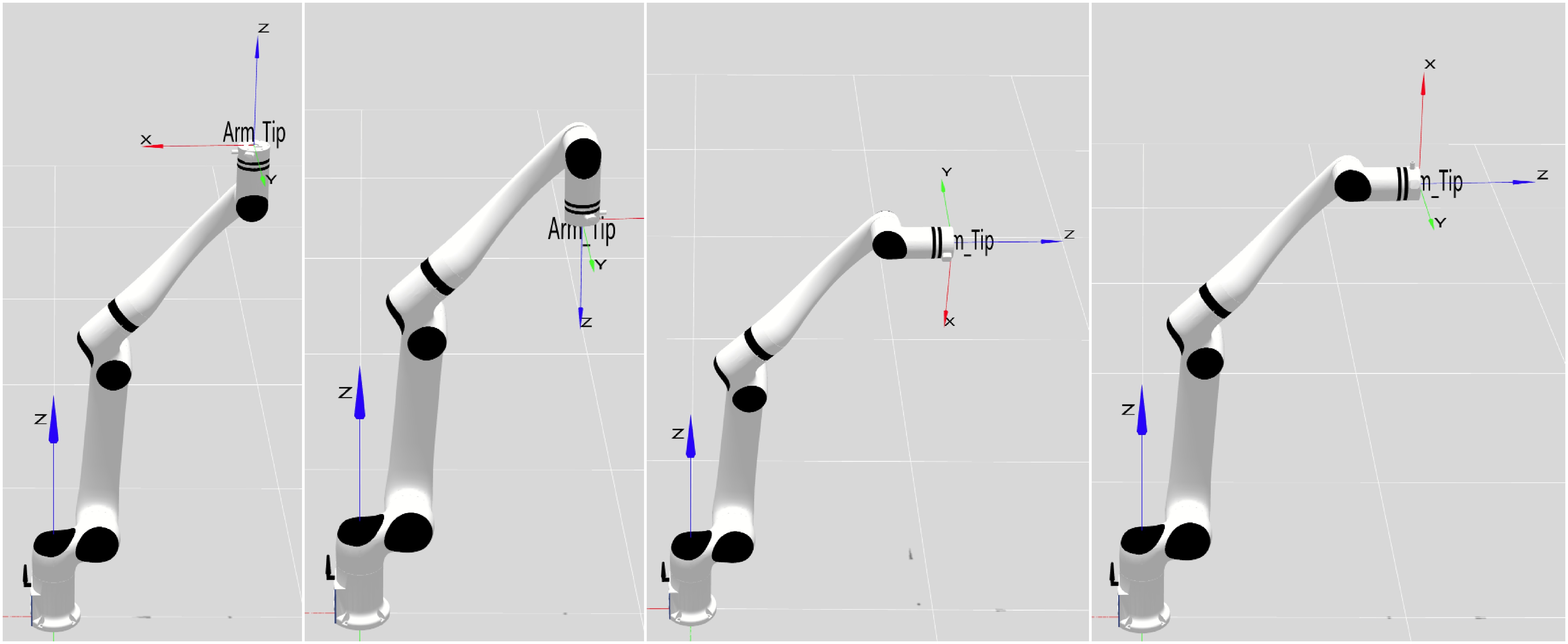
- Calibration should be performed by using the points customized by users according to the actual installation state of the robotic arm and the working range of the end of the robotic arm. When the customized calibration points are defined, obvious attitude differences are required between the customized calibration points (The Z-axes of the end of the robotic arm at the 4 customized calibration points should not lie on the same plane). The customized calibration points can be defined according to four attitudes, namely the attitude with the Z-axis of the end of the robotic arm facing up, the attitude with the X-axis of the end of the robotic arm facing up, the attitude with the X-axis of the end of the robotic arm facing down, and the attitude with the Z-axis of the end of the robotic arm facing down.
4.3 Setting Global Waypoints
TIP
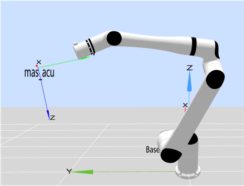
In this case, four global waypoints are needed, namely Initial (the initial point before polishing), Point_1 (the start point of a polishing cycle), Point_2 (the end point of the polishing cycle), and Point_3 (the end point of polishing). Since the algorithm takes the Z-axis of the tool coordinate system as the reference line of force tracking + attitude adaptation, the end tool coordinate system needs to be configured as the normal direction of the polishing contact surface, with the Z-axis pointing to the contact surface, as shown in the figure below.
The specific process of setting the global waypoints is as follows:
On the the home page of the HMI, click Data Management to go to the Data Management page, click Global Waypoints to go to the Global Waypoints tab, then click the green plus sign in the upper right corner.
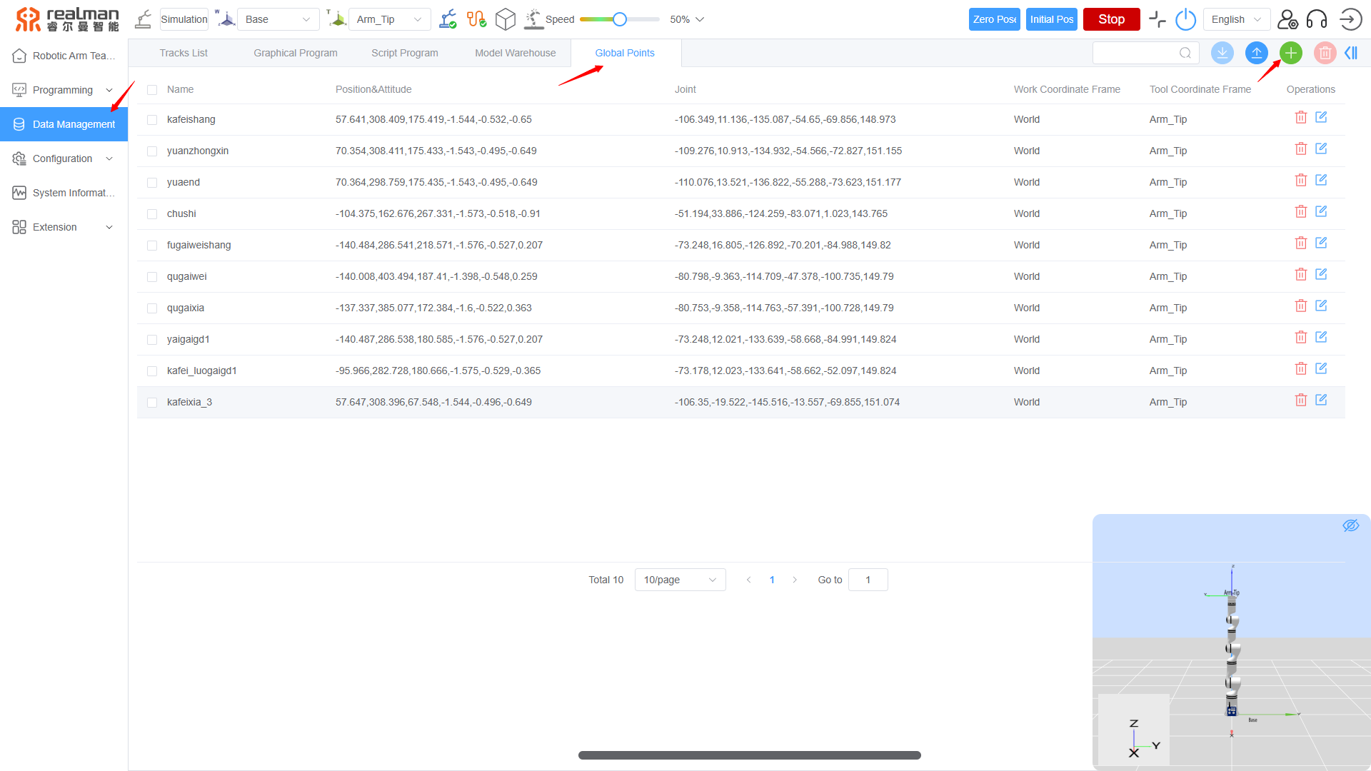
Click the blue eye icon in the lower right corner to open the 3D simulation space for easy observation of the status of the set global waypoints.
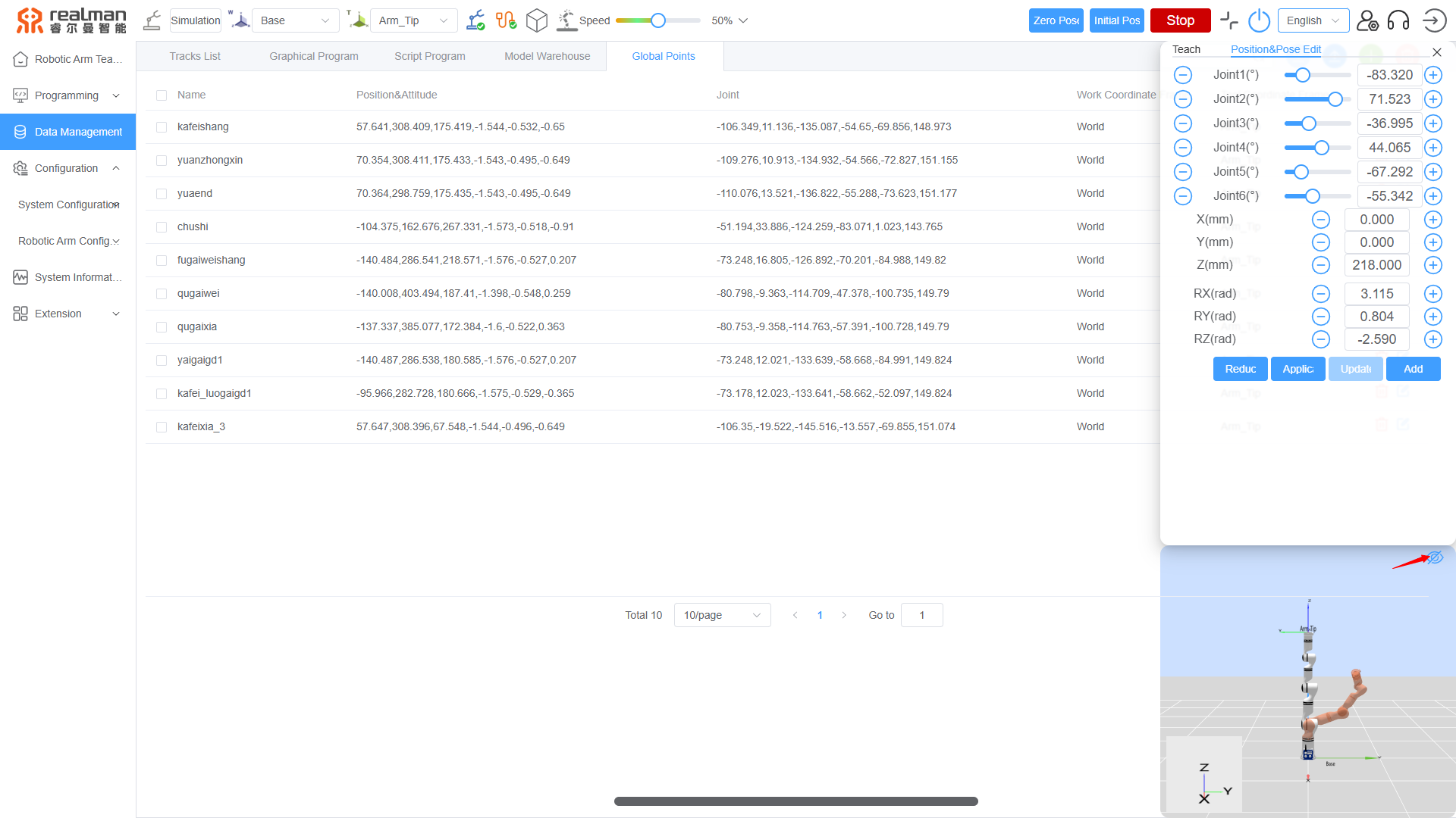
Click the Add Waypoint button to add and name a global waypoint, and then save.
4.4 Setting the Tool Coordinate System
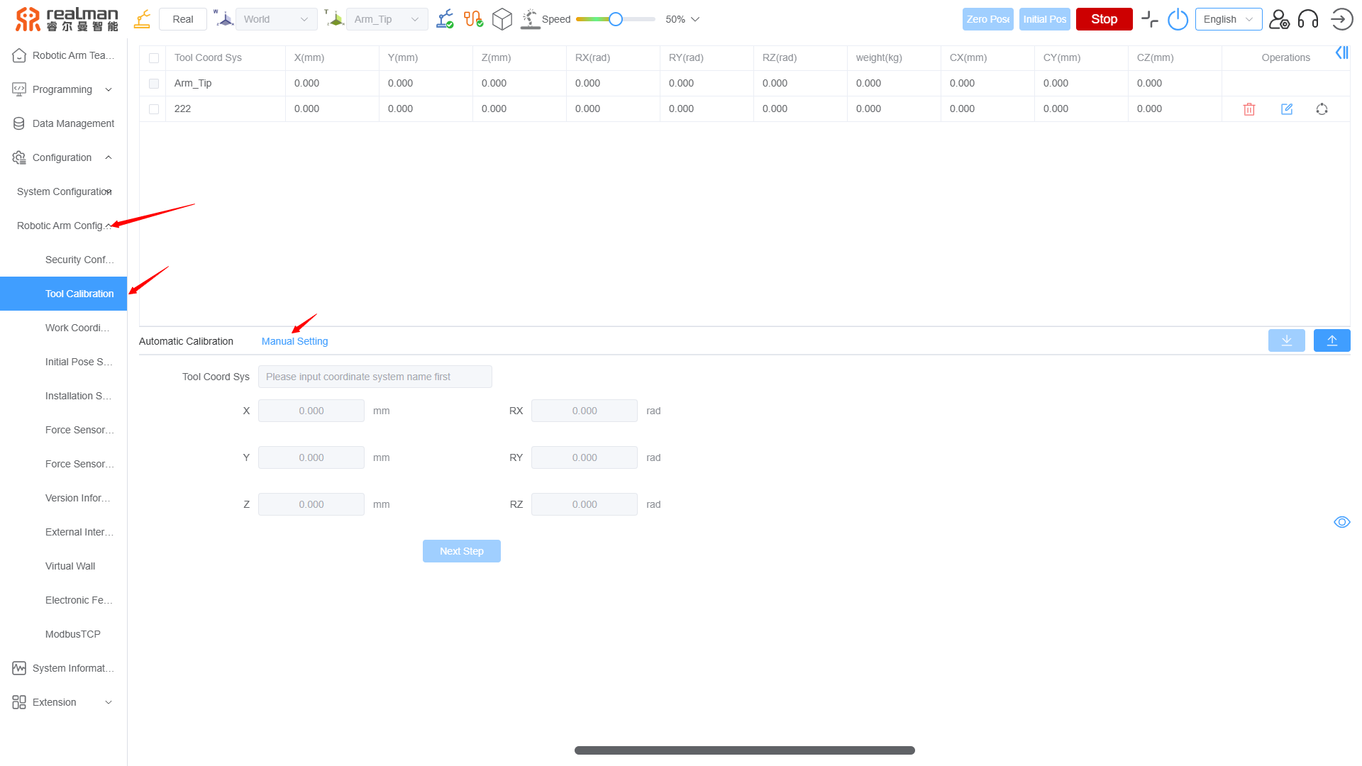
The automatic calibration function of the robotic arm cannot adapt to the custom structures of most polishing heads, so that it is necessary to manually calibrate the tool coordinate system.
Manual calibration process:
- On the home page of the HMI, click Configuration > Robotic Arm Configuration > Tool Coordinate System Calibration in the left menu bar to go to the Tool Coordinate System Calibration page.
- Click Manual Setting to go to the Manual Calibration page.
- Fill in the name of the tool coordinate system, fill in the values of the parameters according to the actual physical dimensions (length, diameter, installation offset, etc.) of the current polishing head, and click Next to complete calibration.
4.5 Programming Control
When users need to conduct secondary development on this case through a C++/Python program, refer to the Appendix for relevant resources to download the API2 interface library, and select and download the corresponding source file of the case according to the control method.
Then, apply the source file of the case as described below according to the control method:
Graphical programming case: Click Programming > Graphical Programming > Local Import (in the upper left corner) to upload the downloaded file to the Robotic Arm Teaching for use.
Python programming case: Store the source file of the case in the directory of the Python source code you will write, and then compile the code. After the code is compiled successfully, start the generated executable file directly (the structure of the case file is as follows):
File Structure
  ├─Python_Sandling
  │   └─Sanding_Demo.py  <- Python Example Script
  └─Robotic_Arm
      ├─libs
      │  ├─linux_arm
      │  ├─linux_x86
      │  ├─win_32
      │  └─win_64
      └─__pycache__
Case study of Python programming:
# Sanding_Demo.py
import sys
import os
import time
sys.path.append(os.path.abspath(os.path.join(os.path.dirname(__file__), '..')))
from Robotic_Arm.rm_robot_interface import *
class Sanding_Demo:
def __init__(self, mode: rm_thread_mode_e=None, speed: float=0.3):
# Instantiate the number of robotic arm control threads
self._arm = RoboticArm(mode)
# Connect to the robotic arm and print the connection ID
self._arm.rm_create_robot_arm("192.168.1.18", 8080)
print("Algorithm library version:", self._arm.rm_algo_version())
print("*******Algorithm version: v1.0.0*******")
# Set the number of executions
self.times = 0
self.speed = speed
# Control the robotic arm to the local waypoint
self._arm.rm_movej(self._arm.rm_get_given_global_waypoint("initial")[1]["joint"], int(100 * self.speed), 0, 0, True)
self._arm.rm_movej(self._arm.rm_get_given_global_waypoint("point_1")[1]["joint"], int(50 * self.speed), 0, 0, True)
def run(self, times: int=10):
# Robotic arm plans to the waypoint
self._arm.rm_movej(self._arm.rm_get_given_global_waypoint("point_1")[1]["joint"], int(50 * self.speed), 0, 0, True)
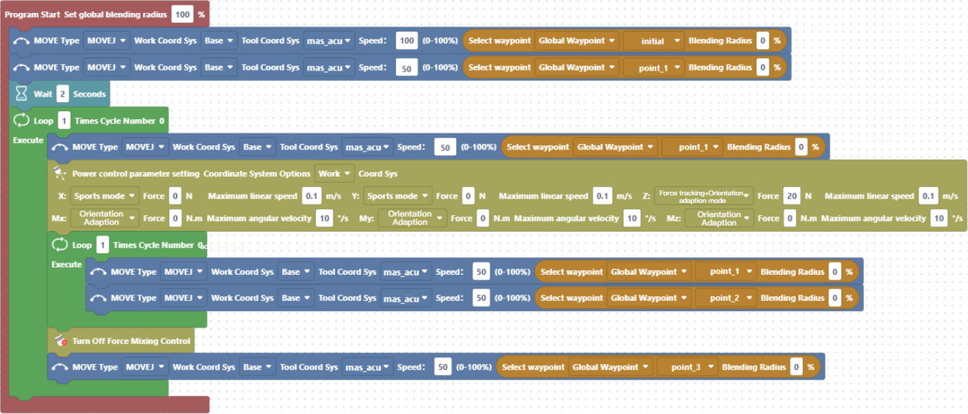
# Configure the force-position hybrid control parameters. In the case of force tracking + attitude adaptation, Rx, Ry, and Rz need to be set to fixed mode, so that the API will automatically recognize it as the attitude adaptation mode.
param = rm_force_position_t(1, 1, (3, 3, 8, 0, 0, 0), (0, 0, 20, 0, 0, 0), (0.1, 0.1, 0.1, 10, 10, 10))
# Enable force-position hybrid control
if self._arm.rm_set_force_position_new(param):
return False
_times = 0
# Cyclic sanding
while _times < times:
self._arm.rm_movel(self._arm.rm_get_given_global_waypoint("point_1")[1]["pose"], int(50 * self.speed), 0, 0, True)
self._arm.rm_movel(self._arm.rm_get_given_global_waypoint("point_2")[1]["pose"], int(50 * self.speed), 0, 0, True)
_times += 1
# Disable force-position hybrid control
if not self._arm.rm_stop_force_position():
self._arm.rm_movej(self._arm.rm_get_given_global_waypoint("point_3")[1]["joint"], int(50 * self.speed), 0, 0, True)
self.times += 1
return True
else:
return False
def __del__(self):
# Delete the robotic arm instance
self._arm.rm_delete_robot_arm()
# Cancel all threads
self._arm.rm_destroy()
if __name__=='__main__':
# Initialize the device
robot = Sanding_Demo(rm_thread_mode_e.RM_TRIPLE_MODE_E)
# Set delay
time.sleep(2)
# Cyclically control the number of workpieces to be sanded
while robot.times < 1:
# Set the number of times to sand the same workpiece in the internal loop
if not robot.run(1):
break- C ++programming case: Store the source file of the case in the specified location, and create the C++ source file to reference and compile it. After the code is compiled successfully, start the generated executable file directly (the structure of the case file is as follows):
File Structure
  ├─CPP_Sanding
  │  ├─Sanding_Demo.cpp  <- C++ Example Source File
  │  └─output
  ├─include
  │  ├─rm_define.h
  │  ├─rm_interface_global.h
  │  ├─rm_interface.h
  │  └─rm_service.h
  ├─linux
  │  ├─linux_arm64_c++_v1.0.4
  │  └─linux_x86_c++_v1.0.4
  └─windows
     ├─win_mingw64_c++_v1.0.4
     ├─win_x64_c++_v1.0.4
     └─win_x86_c++_v1.0.4
Case study of C++ programming:
// Sanding_Demo.cpp

#include <iostream>
#include <unistd.h>
#include <vector>
#include "rm_interface.h"

using namespace std;

class Sanding_Demo
{
private:
    rm_robot_handle *arm_handle;
    // rm_waypoint_t *pose[4];
    vector<rm_waypoint_t*> pose;
    float speed;
public:
    int times;

    bool Run(int times);
    Sanding_Demo(rm_thread_mode_e mode);
    Sanding_Demo(rm_thread_mode_e mode, float speed);
    ~Sanding_Demo();
};

Sanding_Demo::Sanding_Demo(rm_thread_mode_e mode): times(0), speed(0.3)
{
    // Output API version number
    char *version = rm_api_version();
    printf("api version: %s\n", version);

    // Initialize thread mode
    if (rm_init(mode)) {
        printf("Thread mode initialization failed!");
        return;
    }

    // Initialize waypoints
    for (int index = 0; index < 4; index++) {
        pose.push_back(new rm_waypoint_t());
    }

    // Connect to the robotic arm
    arm_handle = rm_create_robot_arm("192.168.1.18", 8080);
    if(arm_handle->id == -1) {
        rm_delete_robot_arm(arm_handle);
        printf("Arm connect err...\n");
    }
    else if(arm_handle != NULL) {
        printf("Connect success,arm id %d\n",arm_handle->id);
    }

    /* Control the robotic arm to local waypoints */
    //Get local waypoints
    if (rm_get_given_global_waypoint(arm_handle, "initial", pose[0]) ||
        rm_get_given_global_waypoint(arm_handle, "point_1", pose[1]) ||
        rm_get_given_global_waypoint(arm_handle, "point_2", pose[2]) ||
        rm_get_given_global_waypoint(arm_handle, "point_3", pose[3])) {
        return;
    }
    else if (rm_movej(arm_handle, pose[0]->joint, int(100 * this->speed), 0, 0, true) ||
        rm_movej(arm_handle, pose[1]->joint, int(50 * this->speed), 0, 0, true)) {
        printf("Movej actions execution failed!");
    }
    else {
        printf("Action initialization succeessful!");
    }
}

// Reconstruct the constructor
Sanding_Demo::Sanding_Demo(rm_thread_mode_e mode, float speed): times(0), speed(speed)
{
    // Output API version number
    char *version = rm_api_version();
    printf("api version: %s\n", version);

    // Initialize thread mode 0
    if (rm_init(mode)) {
        printf("Thread mode initialization failed!");
        return;
    }

    // Connect to the robotic arm
    arm_handle = rm_create_robot_arm("192.168.1.18", 8080);
    if(arm_handle->id == -1) {
        rm_delete_robot_arm(arm_handle);
        printf("Arm connect err...\n");
    }
    else if(arm_handle != NULL) {
        printf("Connect success,arm id %d\n",arm_handle->id);
    }

    /* Control the robotic arm to local waypoints */
    //Get local waypoints
    if (rm_get_given_global_waypoint(arm_handle, "initial", pose[0]) ||
        rm_get_given_global_waypoint(arm_handle, "point_1", pose[1]) ||
        rm_get_given_global_waypoint(arm_handle, "point_2", pose[2]) ||
        rm_get_given_global_waypoint(arm_handle, "point_3", pose[3])) {
        return;
    }
    else if (rm_movej(arm_handle, pose[0]->joint, int(100 * this->speed), 0, 0, true) ||
        rm_movej(arm_handle, pose[1]->joint, int(50 * this->speed), 0, 0, true)) {
        printf("Movej actions execution failed!");
    }
    else {
        printf("Action initialization succeessful!");
    }
}

Sanding_Demo::~Sanding_Demo()
{
    // Delete the robotic arm instance
    rm_delete_robot_arm(arm_handle);
    // Cancel all threads
    rm_destroy();
}

bool Sanding_Demo::Run(int times)
{
    // Robotic arm plans to waypoints
    rm_movej(arm_handle, pose[1]->joint, int(50 * this->speed), 0, 0, true);

    /* Enable force-position hybrid control mode. In the case of force tracking + attitude adaptation, Rx, Ry, and Rz need to be set to fixed mode, so the API will automatically recognize it as the attitude adaptation mode.*/
    // Parameter configuration
    rm_force_position_t param = {
        1,  // Sensor: One-dimensional force (0), Six-dimensional force (1)
        1,  // Force coordinate system: Base coordinate system (0), Tool coordinate system (1)
        {3, 3, 8, 0, 0, 0},  // Torque mode array of each axis
        {0, 0, 20, 0, 0, 0},  // Expected force/torque array of each axis
        {0.1, 0.1, 0.1, 10, 10, 10}  // Maximum linear velocity/maximum angular velocity limit array of each axis
    };
    // Enable mode
    if (rm_set_force_position_new(arm_handle, param)) {
        return false;
    }

    // Cyclic sanding
    int _times = 0;
    while (_times < times) {
        rm_movel(arm_handle, pose[1]->pose, int(50 * this->speed), 0, 0, true);
        rm_movel(arm_handle, pose[2]->pose, int(50 * this->speed), 0, 0, true);
        _times++;
    }

    // Disable force-position hybrid control
    if (!rm_stop_force_position(arm_handle)) {
        rm_movej(arm_handle, pose[3]->joint, int(50 * this->speed), 0, 0, true);
        this->times++;
        return true;
    } else {
        return false;
    }
}


int main() {
    // Initialize the device
    Sanding_Demo robot(RM_TRIPLE_MODE_E);

    // Set delay
    sleep(2);

    // Cyclically control the number of workpieces to be sanded
    while (robot.times < 1) {
        // Set the number of times to sand the same workpiece in the internal loop
        if (!robot.Run(1)) {
            break;
        }
    }

    system("pause");
    return 0;
}
V. Introduction to Algorithm Functions
The main working scenario of the autonomous polishing workstation is for polishing workpieces with curved surfaces. In the surface force tracking scenario, if there is no attitude adaptation, the end workpiece will not fit the surface. The traditional method for solving this problem is using many points to fit the surface, resulting in a huge workload of debugging and extremely low polishing efficiency.
Accordingly, we have proposed a constant force tracking and attitude adaption algorithm based on our various series of robotic arms, which will perfectly solve this problem. Given only two points A to B, the robotic arm will adapt to surface changes, adjust its attitude autonomously, and keep the end tool tracking the contact surface with constant force.
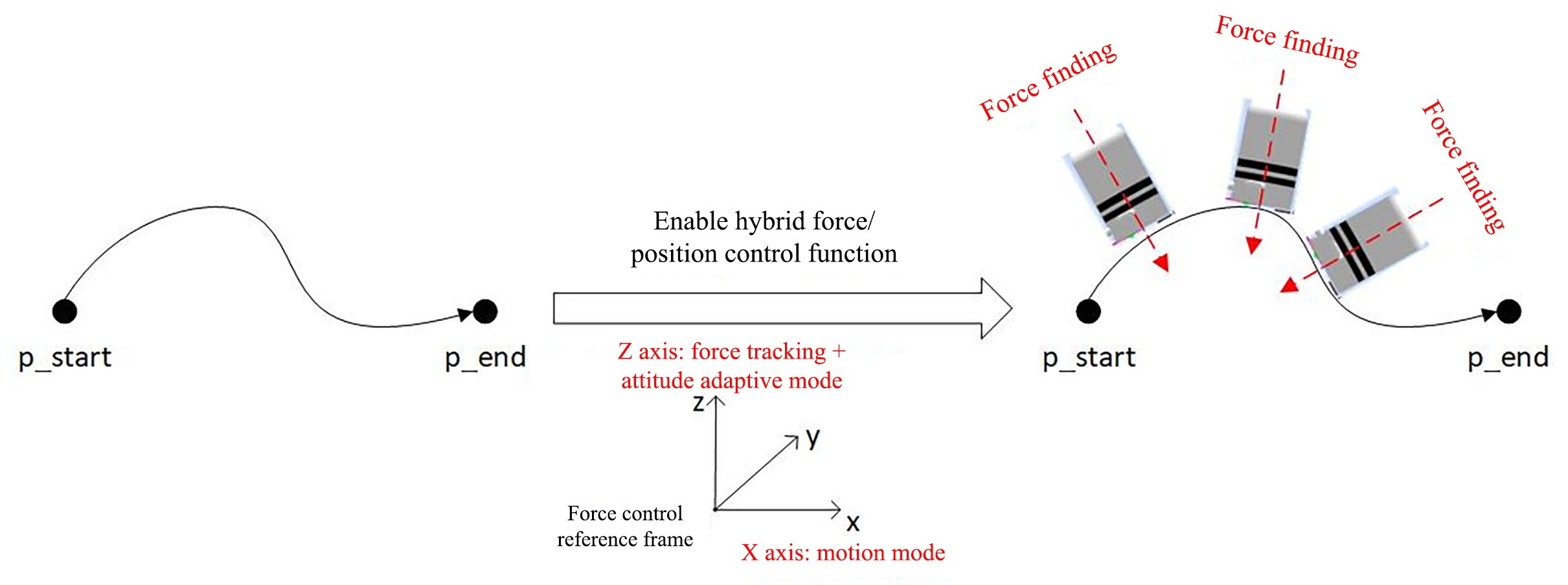
This mode can only be turned on in the Z direction of the force control reference coordinate system, which must be the tool coordinate system. After this mode is turned on, any mode set in the Rx, Ry, or Rz direction of the force control reference coordinate system will not take effect. This mode maintains a given desired force/torque on the coordinate axis, and the attitude of the force control reference coordinate system in the Rx, Ry and Rz directions can be automatically adjusted according to changes of the contact environment.
This mode is mainly used in constant force tracking scenarios where the end tool contacts a complex curved surface or an unknown shape. When the curved surface contacted by the tool at the end of the robotic arm changes, the end of the robotic arm will actively adjust its attitude according to the change in the shape of the curved surface, so as to fit closely with the contact environment. This attitude adaptive technology allows users to use a small number of teaching points, and do not need to pay too much attention to the attitude at the teaching points to achieve constant force tracking that fit closely with complex surfaces.
VI. Description of Algorithm Interfaces
6.1 Description of Python Interface
Set the force and position hybrid control function
- Function prototype
pythonrm_set_force_position_new(self, param: rm_force_position_t) -> int- Parameters
Parameter Type Description paramrm_force_position_tForce and position hybrid control parameter rm_force_position_t:
Property Type Description modeint0 - Force control with the working coordinate system; 1 - Force control with the tool coordinate system. sensorintSensor: 0 - One-dimensional force; 1 - Six-dimensional force. control_modeintModes in 6 directions (Fx, Fy, Fz, Mx, My, Mz): 0 - Fixed mode; 1- Floating mode; 2 - Spring mode; 3 - Motion mode; 4 - Force tracking mode; 8 - Force tracking + attitude adaption mode (Mode 8 is only effective for the Fz direction of the tool coordinate system). desired_forceintThe desired force/torque maintained by the force control axis. The set desired force/torque will be effective only when the force control mode of the force control axis is the force tracking mode. The unit is N. limit_velintThe maximum linear velocity and maximum angular velocity of the force control axis, which are only effective for the direction in which force control is turned on. The maximum linear velocity of the x, y, and z axes is in m/s, and the maximum angular velocity of the rx, ry, and rz axes is in °/s. - Return values: Status codes of function execution
Value Type Description 0 intSucceeded. 1 intThe controller returns false, indicating parameter error or robotic arm status error. -1 intData transmission failed, indicating that a problem occurs during communication. -2 intData reception failed, indicating that a problem occurs during communication or the controller failed to return a value for a long time. -3 intReturn value parsing failed, indicating that the received data is in an incorrect formate or incomplete. - Examples of use
pythonfrom Robotic_Arm.rm_robot_interface import * # Instantiate the RoboticArm class arm = RoboticArm(rm_thread_mode_e.RM_TRIPLE_MODE_E) # Create a robotic arm connection and print the connection ID handle = arm.rm_create_robot_arm("192.168.1.18", 8080) print(handle.id) arm.rm_movej_p([0.2, 0, 0.3, 3.142, 0, 0], 20, 0, 0, 1) param = rm_force_position_t(1, 1, (3, 3, 8, 0, 0, 0), (0, 0, 20, 0, 0, 0), (0.1, 0.1, 0.1, 10, 10, 10)) for i in range(3): result1 = arm.rm_movel([0.2, 0, 0.3, 3.142, 0, 0], 20, 0, 0, 1) result2 = arm.rm_set_force_position_new(param) result3 = arm.rm_movel([0.3, 0, 0.3, 3.142, 0, 0], 20, 0, 0, 1) arm.rm_stop_force_position() arm.rm_delete_robot_arm()Force-position hybrid control stop function
- Prototype method
pythonrm_stop_force_position(self) -> int- Return values: Status codes of function execution
Value Type Description 0 intSucceeded. 1 intThe controller returns false, indicating parameter error or robotic arm status error. -1 intData transmission failed, indicating that a problem occurs during communication. -2 intData reception failed, indicating that a problem occurs during communication or the controller failed to return a value for a long time. -3 intReturn value parsing failed, indicating that the received data is in an incorrect formate or incomplete.
6.2 Description of C++ Interface
Set the force and position hybrid control function
- Prototype method
c++int rm_set_force_position_new(rm_robot_handle * handle, rm_force_position_t param)- Parameters
Parameter Type Description handlerm_robot_handleRobotic arm handle paramrm_force_position_tForce and position hybrid control parameter rm_robot_handle:
Property Type Description idintid greater than 0 will be returned when the connect succeeded, or -1 when the connection failed. rm_force_position_t:
Property Type Description modeint0 - Force control with the working coordinate system; 1 - Force control with the tool coordinate system. sensorintSensor: 0 - One-dimensional force; 1 - Six-dimensional force. control_modeintModes in 6 directions (Fx, Fy, Fz, Mx, My, Mz): 0 - Fixed mode; 1- Floating mode; 2 - Spring mode; 3 - Motion mode; 4 - Force tracking mode; 8 - Force tracking + attitude adaption mode (Mode 8 is only effective for the Fz direction of the tool coordinate system). desired_forceintThe desired force/torque maintained by the force control axis. The set desired force/torque will be effective only when the force control mode of the force control axis is the force tracking mode. The unit is N. limit_velintThe maximum linear velocity and maximum angular velocity of the force control axis, which are only effective for the direction in which force control is turned on. The maximum linear velocity of the x, y, and z axes is in m/s, and the maximum angular velocity of the rx, ry, and rz axes is in °/s. - Return values: Status codes of function execution
Value Type Description 0 intSucceeded. 1 intThe controller returns false, indicating parameter error or robotic arm status error. -1 intData transmission failed, indicating that a problem occurs during communication. -2 intData reception failed, indicating that a problem occurs during communication or the controller failed to return a value for a long time. -3 intReturn value parsing failed, indicating that the received data is in an incorrect formate or incomplete. - Examples of use
c++rm_force_position_t param = { 1, // Sensor: One-dimensional force (0), Six-dimensional force (1) 1, // Force coordinate system: Base coordinate system (0), Tool coordinate system (1) {3, 3, 8, 0, 0, 0}, // Torque mode array of each axis {0, 0, 20, 0, 0, 0}, // Expected force/torque array of each axis {0.1, 0.1, 0.1, 10, 10, 10} // Maximum linear velocity/maximum angular velocity limit array of each axis }; rm_set_force_position_new(robot_handle, param);Force-position hybrid control stop function
- Prototype method
c++int rm_stop_force_position(rm_robot_handle * handle)- Return values: Status codes of function execution
Value Type Description 0 intSucceeded. 1 intThe controller returns false, indicating parameter error or robotic arm status error. -1 intData transmission failed, indicating that a problem occurs during communication. -2 intData reception failed, indicating that a problem occurs during communication or the controller failed to return a value for a long time. -3 intReturn value parsing failed, indicating that the received data is in an incorrect formate or incomplete.
VII. Demonstration Video
Video won't load? Click to view