Application Integration Case:
Teleoperation of RM65 by Touch Project Overview
This project is an innovative robotic arm case integration solution that combines Touch haptic device produced by 3D Systems with RealMan RM65 robotic arm to create a flexible and efficient control case. According to this case, we can achieve agile movement and precise operation in complex environments to meet diverse operation needs. This is a case for the possibility of realizing this composite robot, and it paves the way for the subsequent development of an autonomous operation system.
If necessary, users can independently develop cases of teleoperation by Touch based on this case for other series of six-axis robotic arms.
Project Background
With the widespread application of robots in fields such as manufacturing, medical care, and rescue, high-precision and low-latency teleoperation systems have become a key requirement for handling complex operating scenarios. However, the teleoperation of traditional robotic arms has problems such as lack of tactile feedback, poor operation accuracy, and unintuitive human-computer interaction, which limits its application in precision operations.
This project integrates highly sensitive Touch haptic device and ultra-lightweight humanoid RM65 robotic arm to build a teleoperation platform with real-time feedback, aiming to solve perception faults in human-computer interaction and improve operation efficiency and safety in complex scenes.
Main Objectives
Achieving precise haptic interaction: Achieving stable and consistent teleoperation by means of two-way data synchronization between Touch and RM65 robotic arm.
Optimizing low-latency communication: Making sure the real-time performance of operation instructions and feedback signals (with target latency < 5 ms) to improve operation fluency.
Expanding application scenarios: Verifying the applicability of the system in fields such as medical assistance, industrial testing, and operations in dangerous environment.
Core Functions
Teleoperation:
- Operation end: Touch captures the user's hand movement information in real time and converts it into robotic arm motion instructions.
- Feedback end (RM65-6F expandable): After the data of the force/torque sensor at the end of the robotic arm is processed, tactile feedback is generated by Touch to simulate real environmental resistance.
Technical Highlights
- Low-latency communication architecture: At the Touch end, the Touch joint information is collected at a frequency of 1000 Hz, and transmitted to the robotic arm through the TCP network cable. Then at the robotic arm end, the movement of the robotic arm can be controlled at a maximum frequency of 200 Hz to ensure signal synchronization.
- Adjustable joint mapping algorithm: Users can change the joint mapping method to adapt to different scenarios.
- Modular design: Standardized hardware interfaces and software protocols support rapid adaptation and construction.
Hardware Environment
Introduction to Hardware Foundation
For details on the unpacking and use of Touch, refer to the Unpacking User Manual. Users must operate and control the servo loop of the haptic device correctly according to the Manual. Touch needs to have sufficient "real-time" performance. When the haptic device is used, a dedicated computer is required to ensure optimal performance and experience. Failure to do so may result in slow, inconsistent, or intermittent communication with the haptic device, causing the device to be suspended or shut down.
The minimum computer configuration requirements are as follows:
- Operating system: 64-bit Windows 10 or 11
- Processor: Intel i5/i7, 5th generation or higher CPU with a minimum frequency of 2.5 GHz
- RAM: Minimum 4 GB
- Graphics card: Minimum 256 MB VRAM (with the latest driver installed)
- Disk space: 512 MB
- Display resolution interface: 1280 x 800 (minimum)
Touch or Touch X: USB 2.0/3.0 port or USB hub that supports USB 2.0/3.0. Whichever card is used, make sure that you are using the latest driver according to the manufacturer's instructions.
RealMan RM65 Series robotic arm: This series of products are 6 DoF robotic arms with a load capability of 5 kg. For a RM65-6F robotic arm, the end contains a six-dimensional force sensor that can be used in conjunction with force and position hybrid control to compensate for the end attitude, and perform force control with Touch's force feedback.
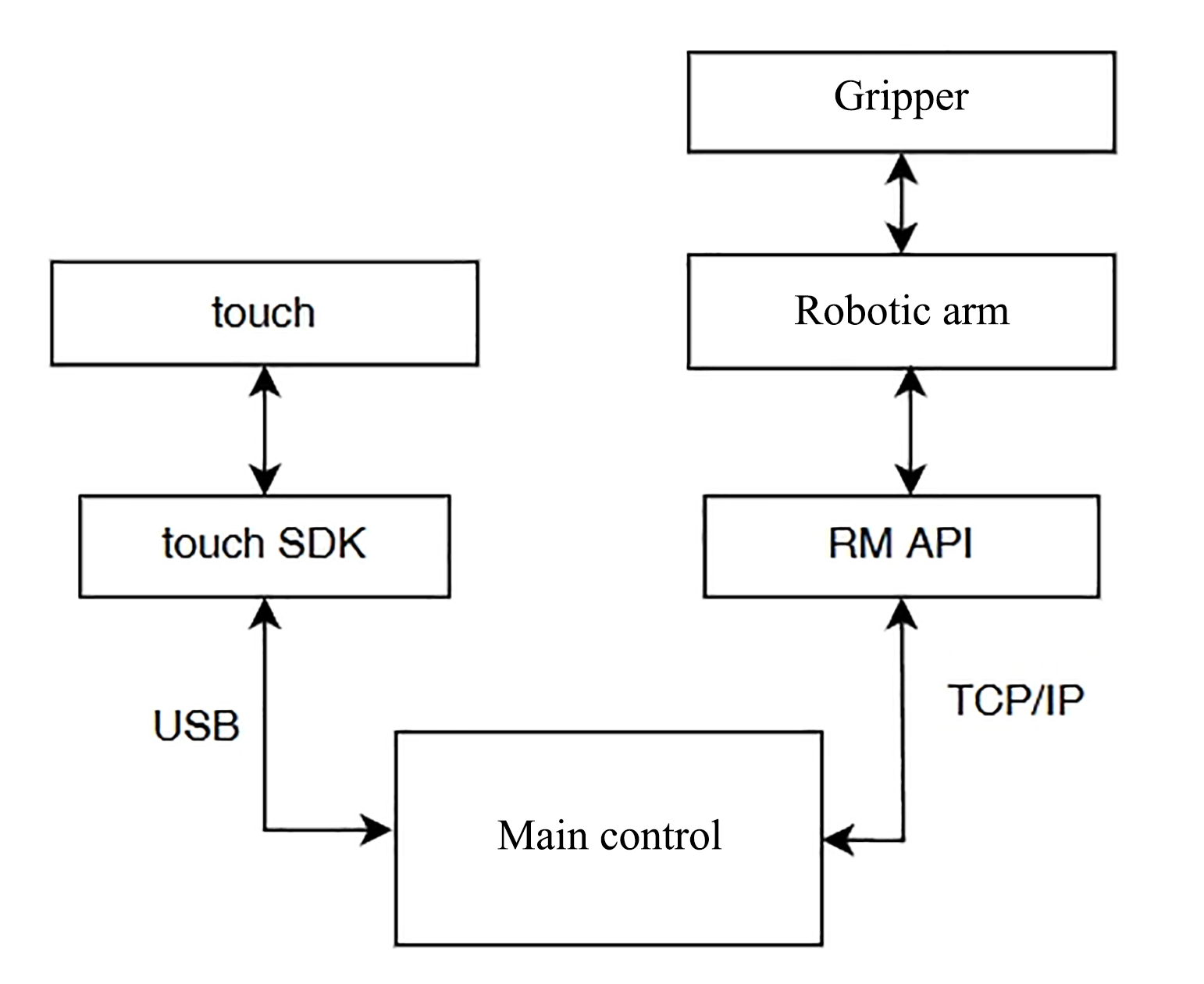
After Touch and robotic arm are powered on normally, you should connect the USB data cable of Touch to the main control, connect the main control and the robotic arm with a network cable, and connect the gripper to the end of the robotic arm. Then all hardware connections are completed.
Hardware Communication Framework
The overall example logic is to read the six-axis joint data of Touch through SDK, then map the data to RM65 robotic arm, and send it down through the unvarnished transmission API of the robotic arm to realize the teleoperation.
Supporting Software
| S/N | Software | Version |
|---|---|---|
| 1 | Third-generation controller | V1.7.0 |
| 2 | API2 | V1.0.7 |
Preparation Stage
Robotic Arm Configuration
After the user's computer is connected to the robotic arm through a network port, the IP address of the computer needs to be configured as 192.168.1.xxx, and the default IP address of the robotic arm when it is delivered at the shop is 192.168.1.18. Open the browser, enter 192.168.1.18 in the URL bar to enter the HMI, and set the end gripper voltage in the expansion bar as 24V to supply power to the clamp.
Touch Configuration
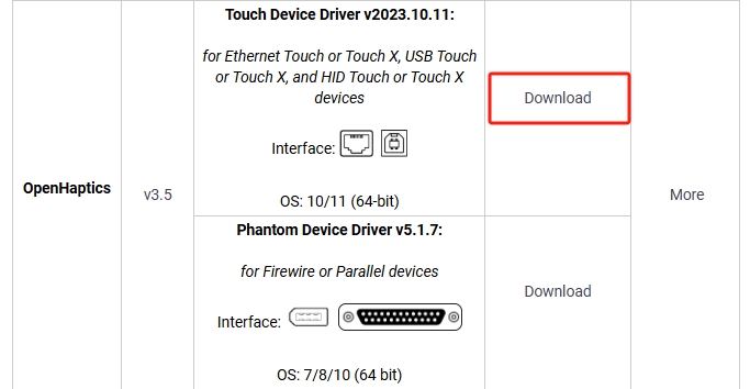
First, go to the Customer Support Center of Touch to download the latest device driver and development kit of Touch.
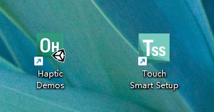
Follow the prompts to install the Touch driver. After the driver is installed, the following two icons will be added to the desktop, the first of which is the demo, and the second is the smart setup.
TIP
- When the computer runs Touch for the first time, it is necessary to click Smart Setup to configure it. Then no further configuration is required in subsequent operation.
- If the connection fails, use Diagnostic for diagnosis. Diagnostic is in the installation path you selected when installing.
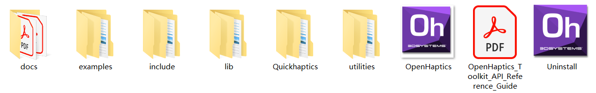
Please visit the Touch Development Kit to download and install the Touch development kit.
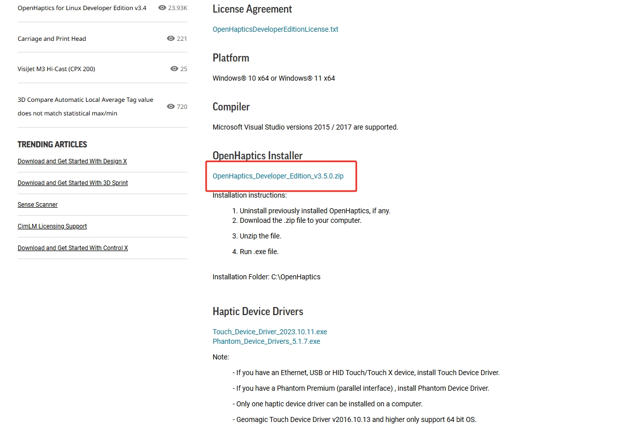
After it is installed, the following files will be automatically generated.
TIP
Please record the file storage path. This article takes D:/openhaptics as an example to illustrate how to configure the development environment in VS2017.
Visual Studio 2017 Installation Configuration
Please download Visual Studio 2017 and double-click the file. If there is no problem with the .Net Framework version, you will come to the Installation page.

Click the
Continuebutton, and the installer begins to prepare the computer for installing Visual Studio.
When Visual Studio is ready, enter the following page.
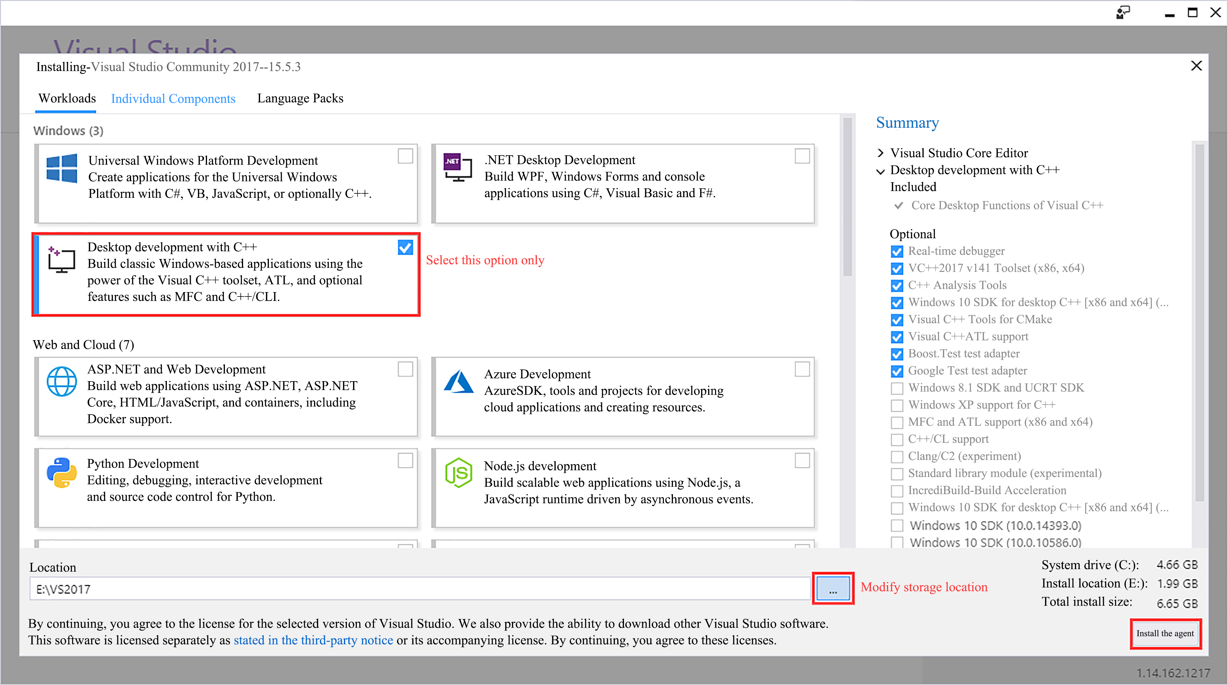
Select
Desktop development with C++and modify the storage location, then clickInstallto start installing Visual Studio. The installation process may take some time, so please wait patiently.TIP
- In addition to development with C/C++ , VS 2017 also supports development languages such as C#, F#, and Visual Basic. You only need to select
Desktop development with C++here. - It is not recommended to set the storage location of VS 2017 on the C drive.

- In addition to development with C/C++ , VS 2017 also supports development languages such as C#, F#, and Visual Basic. You only need to select
After the installation is completed, restart the computer. Then, double-click to launch Visual Studio 2017, and follow the prompts to log in and configure your environment.
Please make changes directly in the VS project pre-established by Touch. Please visit Console and use Visual Studio to open the ConsoleExamples_VS2017.sln solution file. If you are prompted to redefine the solution target, click OK.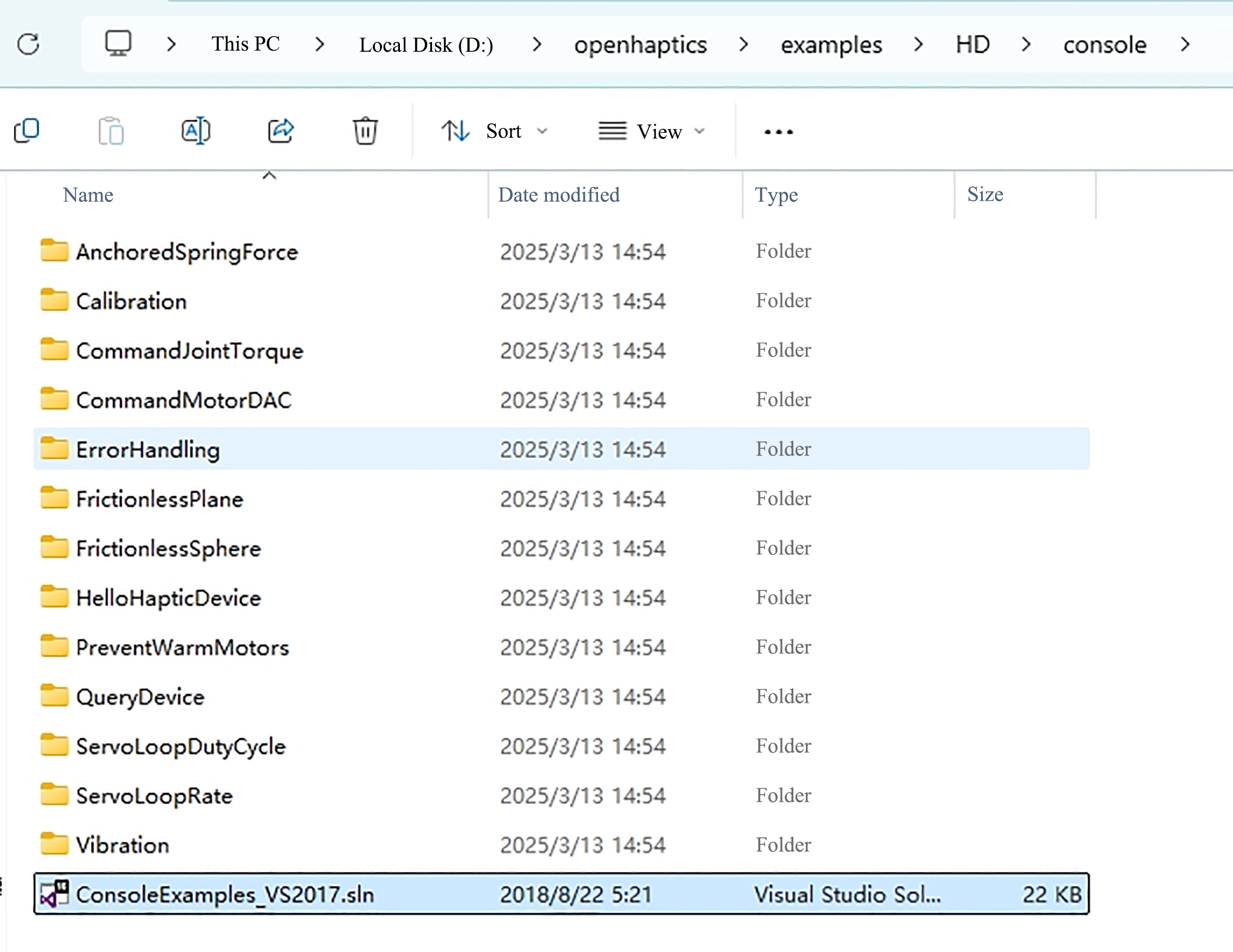 Demonstration content of console examples:
 - AnchoredSpringForce - Simulating spring force;
- Calibration - Examining device information;
- CommandJointTorque- Simulating the spring torque of joint;
- CommandMotorDAC - Directly controlling the movement of the motor in Touch;
- ErrorHandling - Displaying error types;
- FrictionlessPlane - Simulating a frictionless plane;
- FrictionlessSphere - Simulating a frictionless sphere;
- HelloHapticDevice - Simulating a gravity well;
- PreventWarmMotors - Outputting motor temperature information;
- QueryDevice - Printing device information (by invoking the button on the pen);
- ServoLoopDutyCycle - Execution time of printer;
- ServoLoopRate - Printing update frequency;
- Vibration - Simulating sinusoidal vibration;
Select the storage path of the header file.
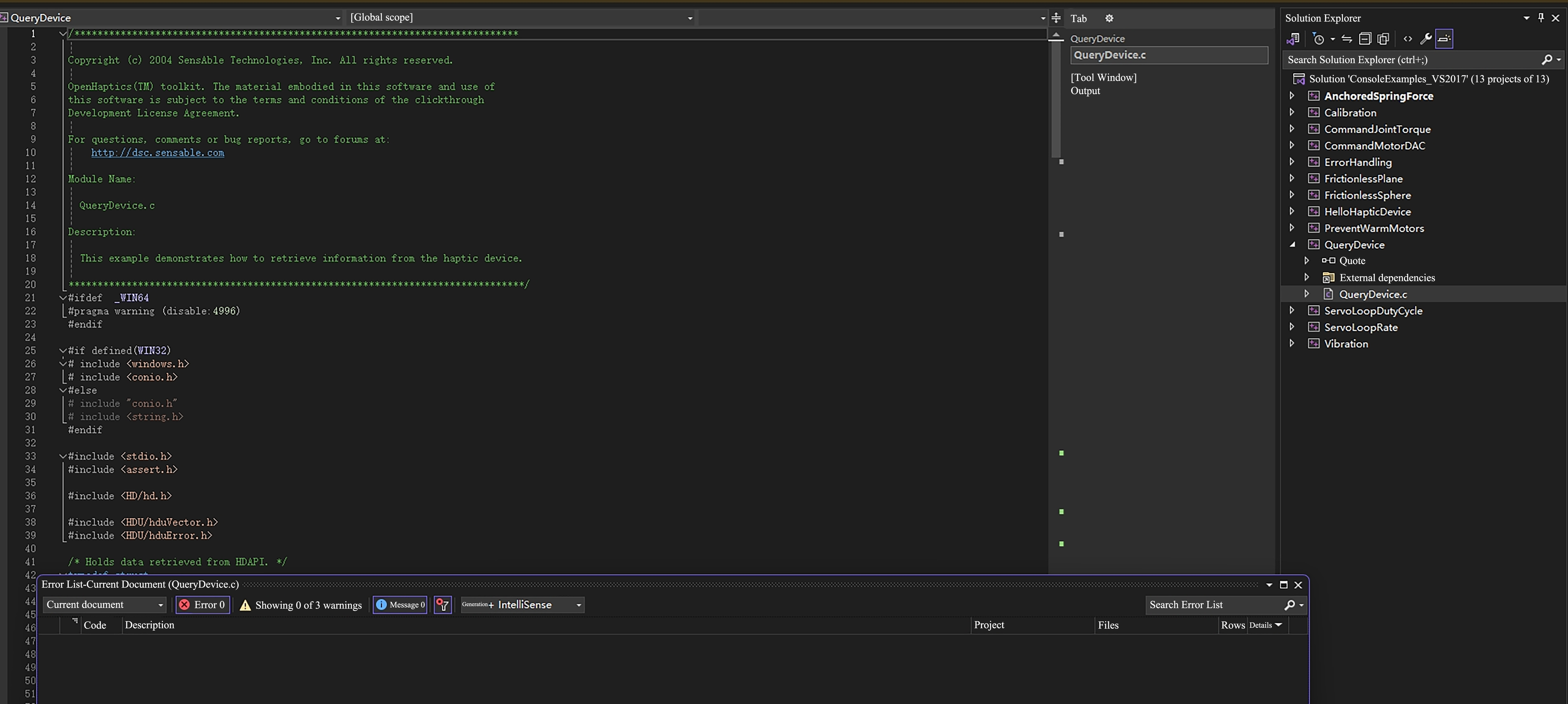
- Click the QueryDevice example on the right to open the QueryDevice.c source file. The source code is displayed on the left. In QueryDevice, you can see the location of the header file reference in the Touch example, and the API header file of the RM65 robotic arm can also be stored under D: \openhaptics\include\HD. Add the RM header file to the source code, and then it can be recognized.
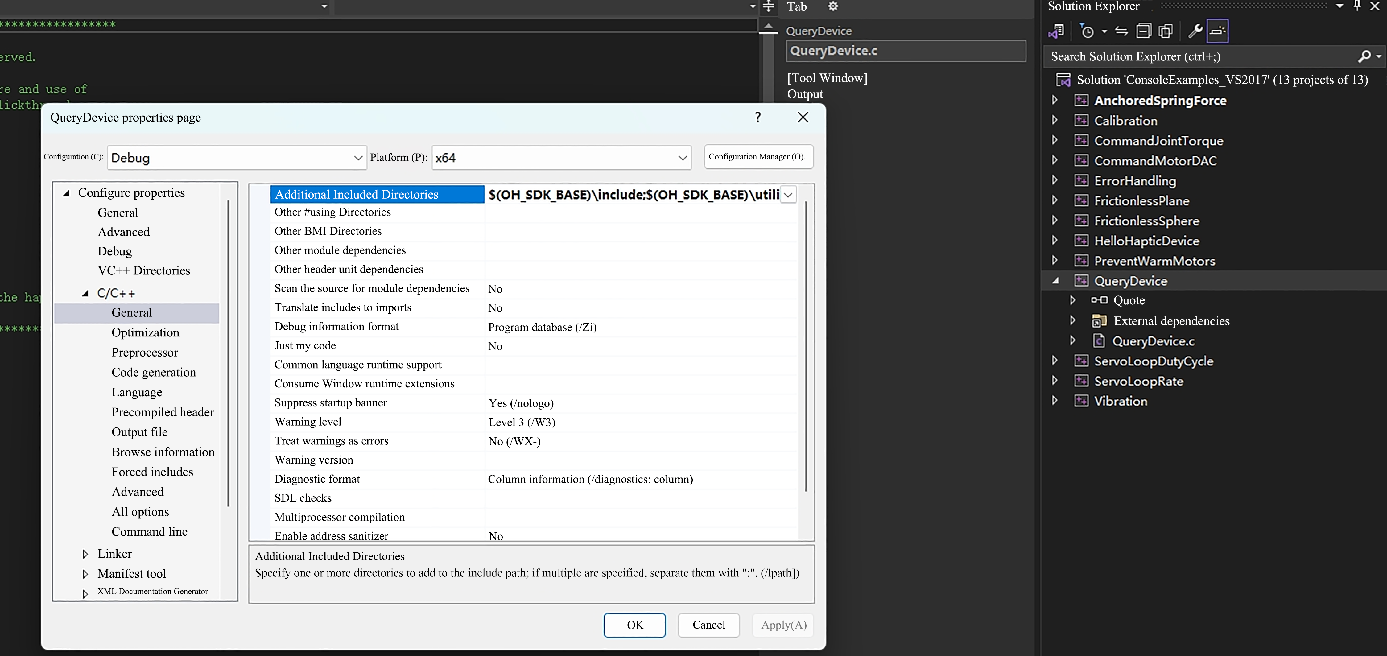
- If you need to store the RM header file separately from the Touch header file, right-click QueryDevice, select Properties, select C/C++ in the left column, and add the path for storing the RM header file in the Additional included directory in General, so that the corresponding path can be used in the code.
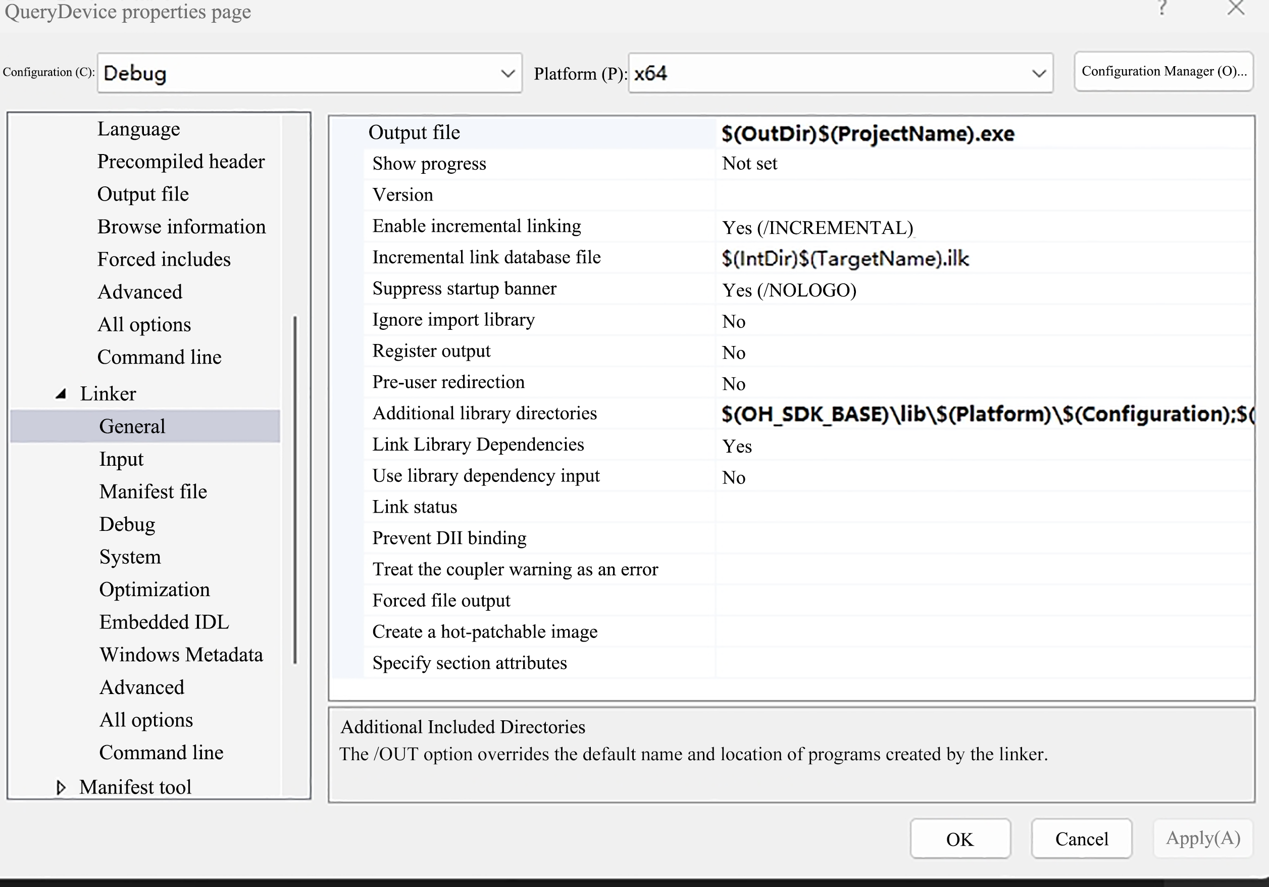
Select Linker, and add the path of the lib file where you store your RM library in the additional library directory in General.
Copy the DLL file to a directory containing the client executables as part of the generation process.
- In the Project Properties page, select Configuration Properties > Build Events > Post build events.
- Select Edit in the "Command line" field to open the edit control and enter the following command:
Cxcopy /y /d "..\lib\api_c.dll" "$(OutDir)"
Now, the environment configuration is basically completed. Go to the source code. The following sample code uses the C ++language API library under Windows. The basic idea is to read the Touch data first, and then map it to the robotic arm. If the environment is configured as C++ language API, change the code file format to cpp, and you can directly copy the following code generation solution.
C/***************************************************************************** Copyright (c) 2004 SensAble Technologies, Inc. All rights reserved. OpenHaptics(TM) toolkit. The material embodied in this software and use of this software is subject to the terms and conditions of the clickthrough Development License Agreement. For questions, comments or bug reports, go to forums at: http://dsc.sensable.com Module Name: QueryDevice.c Description: This example demonstrates how to retrieve information from the haptic device. *******************************************************************************/ #ifdef _WIN64 #pragma warning (disable:4996) #endif #if defined(WIN32) # include <windows.h> # include <conio.h> #else # include "conio.h" # include <string.h> #endif #include <stdio.h> #include <assert.h> #include <HD/hd.h> #include <HDU/hduQuaternion.h> #include <HDU/hduVector.h> #include <HDU/hduError.h> #include <HD/rm_service.h> RM_Service robotic_arm; /* Assumes the unit is a PHANTOM from SensAble Technologies, Inc. */ #define MAX_INPUT_DOF 6 #define MAX_OUTPUT_DOF 6 static int gNumMotors = 0; static int gNumEncoders = 0; static long alMotorDACValuesApp[MAX_OUTPUT_DOF]; static long alMotorDACValuesServo[MAX_OUTPUT_DOF]; /* Holds data retrieved from HDAPI. */ struct OmniState { hduVector3Dd position; //3x1 vector of position hduVector3Dd velocity; //3x1 vector of velocity hduVector3Dd inp_vel1; //3x1 history of velocity used for filtering velocity estimate hduVector3Dd inp_vel2; hduVector3Dd inp_vel3; hduVector3Dd out_vel1; hduVector3Dd out_vel2; hduVector3Dd out_vel3; hduVector3Dd pos_hist1; //3x1 history of position used for 2nd order backward difference estimate of velocity hduVector3Dd pos_hist2; // hduQuaternion rot; hduVector3Dd joints; hduVector3Dd force; //3 element double vector force[0], force[1], force[2] float thetas[7]; int buttons[2]; int buttons_prev[2]; bool lock; bool close_gripper; hduVector3Dd lock_pos; double units_ratio; }; typedef struct { HDboolean m_buttonState; /* Has the device button has been pressed. */ HDboolean n_buttonState; hduVector3Dd m_devicePosition; /* Current device coordinates. */ HDErrorInfo m_error; hduVector3Dd joints; float thetas[7]; float pos[6]; float rm_force[6]; float rm_zero_force[6]; float work_zero[6]; float tool_zero[6]; } DeviceData; static DeviceData gServoDeviceData; HDSchedulerHandle gCallbackHandle = HD_INVALID_HANDLE; /******************************************************************************* Checks the state of the gimbal button and gets the position of the device. *******************************************************************************/ HDCallbackCode HDCALLBACK updateDeviceCallback(void* pUserData) { int nButtons = 0; hdBeginFrame(hdGetCurrentDevice()); /* Retrieve the current button(s). */ hdGetIntegerv(HD_CURRENT_BUTTONS, &nButtons); assert(alMotorDACValuesServo); hdSetLongv(HD_CURRENT_MOTOR_DAC_VALUES, alMotorDACValuesServo); /* In order to get the specific button 1 state, we use a bitmask to test for the HD_DEVICE_BUTTON_1 bit. */ gServoDeviceData.m_buttonState = (nButtons & HD_DEVICE_BUTTON_1) ? HD_TRUE : HD_FALSE; gServoDeviceData.n_buttonState = (nButtons & HD_DEVICE_BUTTON_2) ? HD_TRUE : HD_FALSE; /* Get the current location of the device (HD_GET_CURRENT_POSITION) We declare a vector of three doubles since hdGetDoublev returns the information in a vector of size 3. */ hdGetDoublev(HD_CURRENT_POSITION, gServoDeviceData.m_devicePosition); hdGetDoublev(HD_CURRENT_JOINT_ANGLES, gServoDeviceData.joints); hduVector3Dd gimbal_angles; hdGetDoublev(HD_CURRENT_GIMBAL_ANGLES, gimbal_angles); float t[7] = { 0., gServoDeviceData.joints[0], gServoDeviceData.joints[1], gServoDeviceData.joints[2] - gServoDeviceData.joints[1], gimbal_angles[0], gimbal_angles[1], gimbal_angles[2] }; for (int i = 0; i < 7; i++) gServoDeviceData.thetas[i] = t[i]; /* Also check the error state of HDAPI. */ gServoDeviceData.m_error = hdGetError(); /* Copy the position into our device_data tructure. */ hdEndFrame(hdGetCurrentDevice()); return HD_CALLBACK_CONTINUE; } /******************************************************************************* Checks the state of the gimbal button and gets the position of the device. *******************************************************************************/ HDCallbackCode HDCALLBACK copyDeviceDataCallback(void* pUserData) { DeviceData* pDeviceData = (DeviceData*)pUserData; memcpy(pDeviceData, &gServoDeviceData, sizeof(DeviceData)); return HD_CALLBACK_DONE; } /***************************************************************************** Copies state in thread-safe manner. *****************************************************************************/ HDCallbackCode HDCALLBACK UpdateMotorDACValuesCallback(void* pUserData) { memcpy(alMotorDACValuesServo, alMotorDACValuesApp, sizeof(long) * MAX_OUTPUT_DOF); return HD_CALLBACK_DONE; } /******************************************************************************* This routine allows the device to provide information about the current location of the stylus, and contains a mechanism for terminating the application. Pressing the button causes the application to display the current location of the device. Holding the button down for N iterations causes the application to exit. *******************************************************************************/ void mainLoop(rm_robot_handle* robot_handle) { static const int kTerminateCount = 1000; int buttonHoldCount = 0; int count = 0; bool movej_flag = false; bool gripper_flag = false; printf("*******************mainloop**********************"); /* Instantiate the structure used to capture data from the device. */ DeviceData currentData; DeviceData prevData; /* Perform a synchronous call to copy the most current device state. */ hdScheduleSynchronous(copyDeviceDataCallback, ¤tData, HD_MIN_SCHEDULER_PRIORITY); memcpy(&prevData, ¤tData, sizeof(DeviceData)); /* Run the main loop until the gimbal button is held. */ while (1) { /* Perform a synchronous call to copy the most current device state. This synchronous scheduler call ensures that the device state is obtained in a thread-safe manner. */ hdScheduleSynchronous(copyDeviceDataCallback, ¤tData, HD_MIN_SCHEDULER_PRIORITY); hdScheduleSynchronous(UpdateMotorDACValuesCallback, 0, HD_DEFAULT_SCHEDULER_PRIORITY); for (int i = 1; i < 7; ++i) { // Calculate the absolute difference between current value and previous value double diff = fabs(currentData.thetas[i] - prevData.thetas[i]); // Check if the difference is greater than the threshold if (diff > 0.002) { // If difference is greater, update the value gServoDeviceData.thetas[i] = currentData.thetas[i]; // Update to the threshold value } else { gServoDeviceData.thetas[i] = prevData.thetas[i]; } } gServoDeviceData.pos[0] = -gServoDeviceData.thetas[1] * 70; gServoDeviceData.pos[1] = 60 - (45 * gServoDeviceData.thetas[2]); gServoDeviceData.pos[2] = 85 - (45 * gServoDeviceData.thetas[3]); gServoDeviceData.pos[3] = -gServoDeviceData.thetas[4] * 30; gServoDeviceData.pos[4] = 70 - (20 * gServoDeviceData.thetas[5]); gServoDeviceData.pos[5] = gServoDeviceData.thetas[6] * 30; count++; //int ret0 = Get_Force_Data(m_sockhand, gServoDeviceData.rm_force, gServoDeviceData.rm_zero_force, gServoDeviceData.work_zero, gServoDeviceData.tool_zero); /* If the user depresses the gimbal button, display the current location information. */ if (currentData.m_buttonState && !prevData.m_buttonState) { uint16_t Arm_Err; uint16_t Sys_Err; int ret2 = robotic_arm.rm_movej(robot_handle, gServoDeviceData.pos, 20, 0, 0, 1); printf("*******************pos:\n%f\n%f\n%f\n%f\n%f\n%f\n**********************", gServoDeviceData.pos[0], gServoDeviceData.pos[1], gServoDeviceData.pos[2], gServoDeviceData.pos[3], gServoDeviceData.pos[4], gServoDeviceData.pos[5]); if (ret2 == 0) { movej_flag = !movej_flag; } } else if (currentData.n_buttonState && prevData.n_buttonState) { /* Keep track of how long the user has been pressing the button. If this exceeds N ticks, then terminate the application. */ buttonHoldCount++; if (buttonHoldCount > kTerminateCount) { /* Quit, since the user held the button longer than the terminate count. */ } } else if (!currentData.m_buttonState && prevData.m_buttonState) { /* Reset the button hold count, since the user stopped holding down the stylus button. */ buttonHoldCount = 0; } if (movej_flag) { int ret4 = robotic_arm.rm_movej_canfd(robot_handle, gServoDeviceData.pos, false, 0); //printf("*******************pos:\n%f\n%f\n%f\n%f\n%f\n%f\n**********************", gServoDeviceData.thetas[1], gServoDeviceData.thetas[2], gServoDeviceData.thetas[3], gServoDeviceData.thetas[4], gServoDeviceData.thetas[5], gServoDeviceData.thetas[5]); } if (currentData.n_buttonState && !prevData.n_buttonState) { gripper_flag = !gripper_flag; if (!gripper_flag) { int ret3 = robotic_arm.rm_set_gripper_release(robot_handle, 500, true, 30); printf("******************Gripper_close********************/n"); } if (gripper_flag) { int ret6 = robotic_arm.rm_set_gripper_pick(robot_handle, 500, 1000, true, 0); printf("*****************Gripper_Pick_On************************/n"); } } /* Check if an error occurred. */ if (HD_DEVICE_ERROR(currentData.m_error)) { hduPrintError(stderr, ¤tData.m_error, "Device error detected"); if (hduIsSchedulerError(¤tData.m_error)) { /* Quit, since communication with the device was disrupted. */ fprintf(stderr, "\nPress any key to quit.\n"); getch(); break; } } /* Store off the current data for the next loop. */ memcpy(&prevData, ¤tData, sizeof(DeviceData)); } } void custom_api_log(const char* message, va_list args) { if (!message) { fprintf(stderr, "Error: message is a null pointer\n"); return; } char buffer[1024]; vsnprintf(buffer, sizeof(buffer), message, args); printf(" %s\n", buffer); } /******************************************************************************* Main function. Sets up the device, runs main application loop, cleans up when finished. *******************************************************************************/ int main(int argc, char* argv[]) { HDSchedulerHandle hUpdateHandle = 0; HDErrorInfo error; int result = -1; robotic_arm.rm_set_log_call_back(custom_api_log, 3); result = robotic_arm.rm_init(RM_TRIPLE_MODE_E); if (result != 0) { printf("Initialization failed with error code: %d.\n", result); return -1; } char* api_version = robotic_arm.rm_api_version(); printf("API Version: %s.\n", api_version); const char* robot_ip_address = "192.168.1.19"; int robot_port = 8080; rm_robot_handle* robot_handle = robotic_arm.rm_create_robot_arm(robot_ip_address, robot_port); if (robot_handle == NULL) { printf("Failed to create robot handle.\n"); return -1; } else { printf("Robot handle created successfully: %d\n", robot_handle->id); } /* Initialize the device, must be done before attempting to call any hd functions. */ HHD hHD = hdInitDevice(HD_DEFAULT_DEVICE); if (HD_DEVICE_ERROR(error = hdGetError())) { hduPrintError(stderr, &error, "Failed to initialize the device"); fprintf(stderr, "\nPress any key to quit.\n"); getch(); return -1; } hdGetIntegerv(HD_OUTPUT_DOF, &gNumMotors); hdGetIntegerv(HD_INPUT_DOF, &gNumEncoders); memset(alMotorDACValuesApp, 0, sizeof(long) * MAX_OUTPUT_DOF); memset(alMotorDACValuesServo, 0, sizeof(long) * MAX_OUTPUT_DOF); /* Schedule the main scheduler callback that updates the device state. */ hUpdateHandle = hdScheduleAsynchronous( updateDeviceCallback, 0, HD_MAX_SCHEDULER_PRIORITY); hdEnable(HD_FORCE_OUTPUT); /* Start the servo loop scheduler. */ hdStartScheduler(); if (HD_DEVICE_ERROR(error = hdGetError())) { hduPrintError(stderr, &error, "Failed to start the scheduler"); fprintf(stderr, "\nPress any key to quit.\n"); getch(); return -1; } /* Run the application loop. */ mainLoop(robot_handle); /* For cleanup, unschedule callbacks and stop the servo loop. */ hdStopScheduler(); hdUnschedule(hUpdateHandle); hdUnschedule(gCallbackHandle); hdDisableDevice(hHD); return 0; } /******************************************************************************/The exit, right-click the QueryDevice example, select Regenerate, and record the generation path.
Operation Demonstration
Under the generated path, find the executable .exe file, double-click to open it, wait for the successful connection prompt, and then press the upper button of the Touch handle to make the robotic arm reach the same attitude as Touch. Then, the robotic arm will automatically start to follow the movement of Touch. The lower button of the Touch handle is used to close and open of the gripper. Press once to switch the gripper state.
Video won't load? Click to view
Key Code Analysis
Defining the structure information for storing the device information.
C// Status Information Structure in Touch SDK struct OmniState { hduVector3Dd position; //3x1 vector of position hduVector3Dd velocity; //3x1 vector of velocity hduVector3Dd inp_vel1; //3x1 history of velocity used for filtering velocity estimate hduVector3Dd inp_vel2; hduVector3Dd inp_vel3; hduVector3Dd out_vel1; hduVector3Dd out_vel2; hduVector3Dd out_vel3; hduVector3Dd pos_hist1; //3x1 history of position used for 2nd order backward difference estimate of velocity hduVector3Dd pos_hist2; hduQuaternion rot; hduVector3Dd joints; hduVector3Dd force; //3 element double vector force[0], force[1], force[2] float thetas[7]; int buttons[2]; int buttons_prev[2]; bool lock; bool close_gripper; hduVector3Dd lock_pos; double units_ratio; }; // Structure for Mapping to Robot Arm and Sending Information to Robot Arm typedef struct { HDboolean m_buttonState; /* Has the device button has been pressed. */ HDboolean n_buttonState; hduVector3Dd m_devicePosition; /* Current device coordinates. */ HDErrorInfo m_error; hduVector3Dd joints; float thetas[7]; float pos[6]; float rm_force[6]; float rm_zero_force[6]; float work_zero[6]; float tool_zero[6]; } DeviceData;Real-time collecting Touch data.
C// Obtain data from Touch, including the states of six joints and two buttons HDCallbackCode HDCALLBACK updateDeviceCallback(void *pUserData) { int nButtons = 0; hdBeginFrame(hdGetCurrentDevice()); /* Retrieve the current button(s). */ hdGetIntegerv(HD_CURRENT_BUTTONS, &nButtons); assert(alMotorDACValuesServo); hdSetLongv(HD_CURRENT_MOTOR_DAC_VALUES, alMotorDACValuesServo); /* In order to get the specific button 1 state, we use a bitmask to test for the HD_DEVICE_BUTTON_1 bit. */ gServoDeviceData.m_buttonState = (nButtons & HD_DEVICE_BUTTON_1) ? HD_TRUE : HD_FALSE; gServoDeviceData.n_buttonState = (nButtons & HD_DEVICE_BUTTON_2) ? HD_TRUE : HD_FALSE; /* Get the current location of the device (HD_GET_CURRENT_POSITION) We declare a vector of three doubles since hdGetDoublev returns the information in a vector of size 3. */ hdGetDoublev(HD_CURRENT_POSITION, gServoDeviceData.m_devicePosition); hdGetDoublev(HD_CURRENT_JOINT_ANGLES, gServoDeviceData.joints); hduVector3Dd gimbal_angles; hdGetDoublev(HD_CURRENT_GIMBAL_ANGLES, gimbal_angles); float t[7] = { 0., gServoDeviceData.joints[0], gServoDeviceData.joints[1], gServoDeviceData.joints[2] - gServoDeviceData.joints[1], gimbal_angles[0], gimbal_angles[1], gimbal_angles[2] }; // Touch Data Acquisition for (int i = 0; i < 7; i++) gServoDeviceData.thetas[i] = t[i]; /* Also check the error state of HDAPI. */ gServoDeviceData.m_error = hdGetError(); /* Copy the position into our device_data tructure. */ hdEndFrame(hdGetCurrentDevice()); return HD_CALLBACK_CONTINUE; }Remapping the data to the robotic arm.
Since Touch and RM robotic arm has different configurations and numerical ranges, a self-set calculation method is required. In this article, the motion range of RM robotic arm is aligned with that of Touch. For example, the motion range of Touch’s Joint 3 is from -0.7 to 1.2, and that of RM65 robotic arm joint 3 is from -178° to 178°. The mapping relationship between the two ranges is calculated to obtain the relationship formula, which is then used to update the data obtained by Touch and issue the data to control the robotic arm. Since the data of Touch fluctuates, a filtering algorithm can also be added to smoothly control the robotic arm.Cfor (int i = 1; i < 7; ++i) { // Calculate the absolute difference between current value and previous value double diff = fabs(currentData.thetas[i] - prevData.thetas[i]); // Check if the difference is greater than the threshold // Simple Filtering if (diff > 0.002) { // If difference is greater, update the value gServoDeviceData.thetas[i] = currentData.thetas[i]; // Update to the threshold value } else { gServoDeviceData.thetas[i] = prevData.thetas[i]; } } // Mapping Relationship Setting gServoDeviceData.pos[0] = -gServoDeviceData.thetas[1] * 70; gServoDeviceData.pos[1] = 60 - (45 * gServoDeviceData.thetas[2]); gServoDeviceData.pos[2] = 85 - (45 * gServoDeviceData.thetas[3]); gServoDeviceData.pos[3] = -gServoDeviceData.thetas[4] * 30; gServoDeviceData.pos[4] = 70 - (20 * gServoDeviceData.thetas[5]); gServoDeviceData.pos[5] = gServoDeviceData.thetas[6] * 30; count++;Adjusting the interval of issuance. Touch's issuing frequency is 1000 Hx, while the preferable frequency for controlling the unvarnished transmission of the robotic arm around 100 Hz, so that it is necessary to adjust this difference.
C// Detect the upper button of the Touch controller. If it is pressed, synchronize the posture of the robotic arm with that of the Touch. if (currentData.m_buttonState && !prevData.m_buttonState) { uint16_t Arm_Err; uint16_t Sys_Err; int ret2 = robotic_arm.rm_movej(robot_handle, gServoDeviceData.pos, 20, 0, 0, 1); printf("*******************pos:\n%f\n%f\n%f\n%f\n%f\n%f\n**********************", gServoDeviceData.pos[0], gServoDeviceData.pos[1], gServoDeviceData.pos[2], gServoDeviceData.pos[3], gServoDeviceData.pos[4], gServoDeviceData.pos[5]); if (ret2 == 0) { movej_flag = !movej_flag; } }Gripper control method.
C// The gripper control takes the initial gripper state as the gripper_flag. Each press toggles the state to achieve opening and closing. if (currentData.n_buttonState && !prevData.n_buttonState) { gripper_flag = !gripper_flag; if (!gripper_flag) { int ret3 = robotic_arm.rm_set_gripper_release(robot_handle, 500, true, 30); printf("******************Gripper_close********************/n"); } if (gripper_flag) { int ret6 = robotic_arm.rm_set_gripper_pick(robot_handle, 500, 1000, true, 0); printf("*****************Gripper_Pick_On************************/n"); } }For RM65-6F six-dimensional force robotic arm, refer to the following code for the six-dimensional force information of the robotic arm, and give Touch force feedback information through Touch's Motor Control SDK to complete force feedback control.
Cif (movej_flag) { alMotorDACValuesApp[0] = -gServoDeviceData.rm_zero_force[0] * 500; alMotorDACValuesApp[1] = gServoDeviceData.rm_zero_force[2] * 500; alMotorDACValuesApp[2] = gServoDeviceData.rm_zero_force[1] * 500; int ret4 = robotic_arm.rm_movej_canfd(robot_handle, gServoDeviceData.pos, false, 0); //printf("*******************pos:\n%f\n%f\n%f\n%f\n%f\n%f\n**********************", gServoDeviceData.thetas[1], gServoDeviceData.thetas[2], gServoDeviceData.thetas[3], gServoDeviceData.thetas[4], gServoDeviceData.thetas[5], gServoDeviceData.thetas[5]); }
Update Log
| Update Date | Update Content | Version No. |
|---|---|---|
| April 11, 2025 | Initiation | v1.0.0 |
FAQs
When a configuration error is found in the API header file, check whether the settings in Properties are correct and whether there is an error prompt in VS2017.
When it is reported that msvcp140.dll or any other version is missing when running an executable .exe file, directly search for a new file online, and put it in the project folder, or replace the existing one on your computer.
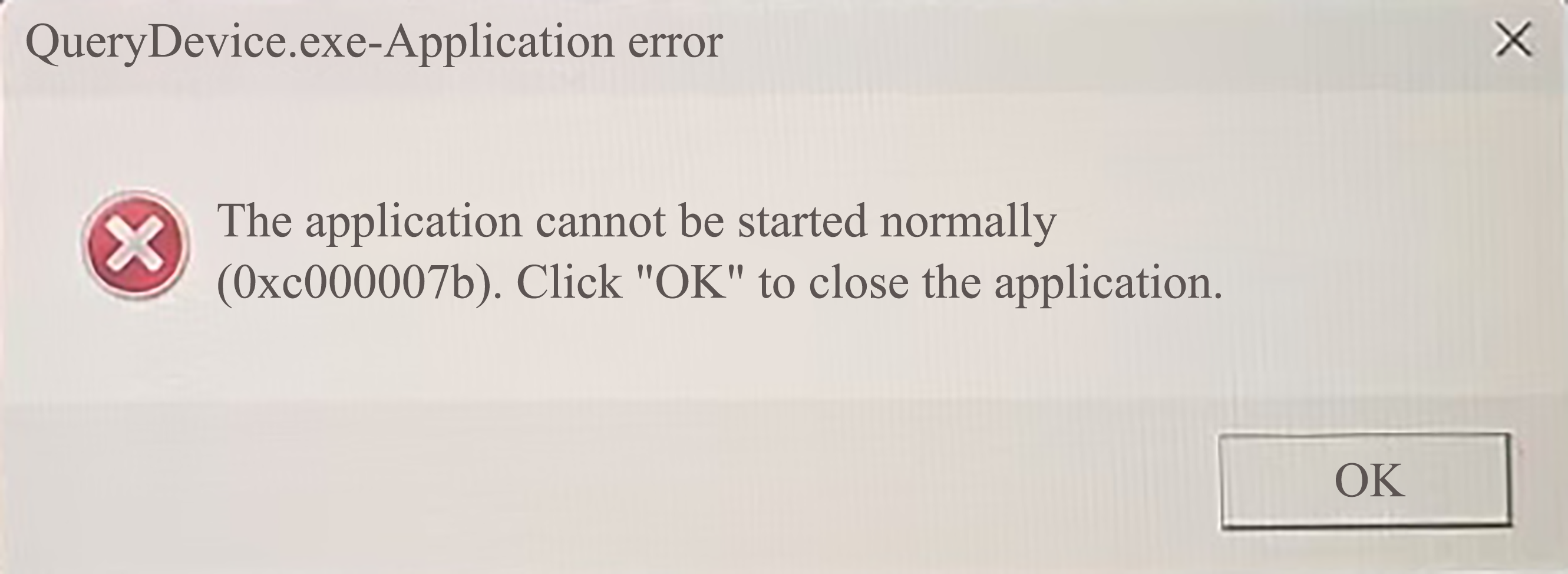
When an error is reported when launching the application, reinstall the Touch driver.