Blog:
External Emergency Stop Button Box Button Box Wiring Installation
The external emergency stop button box has the circuit-type IO emergency stop or IO1 multiplexed emergency stop function. After the circuit-type IO emergency stop is triggered, the robotic arm is powered off and needs to be released from the emergency stop state before operation.
WARNING
- The third-generation controller only supports IO1 multiplexed emergency stop for emergency stop.
- This document takes the fourth-generation controller as an example, and the third-generation controller can also refer to this document for operation.
Introduction
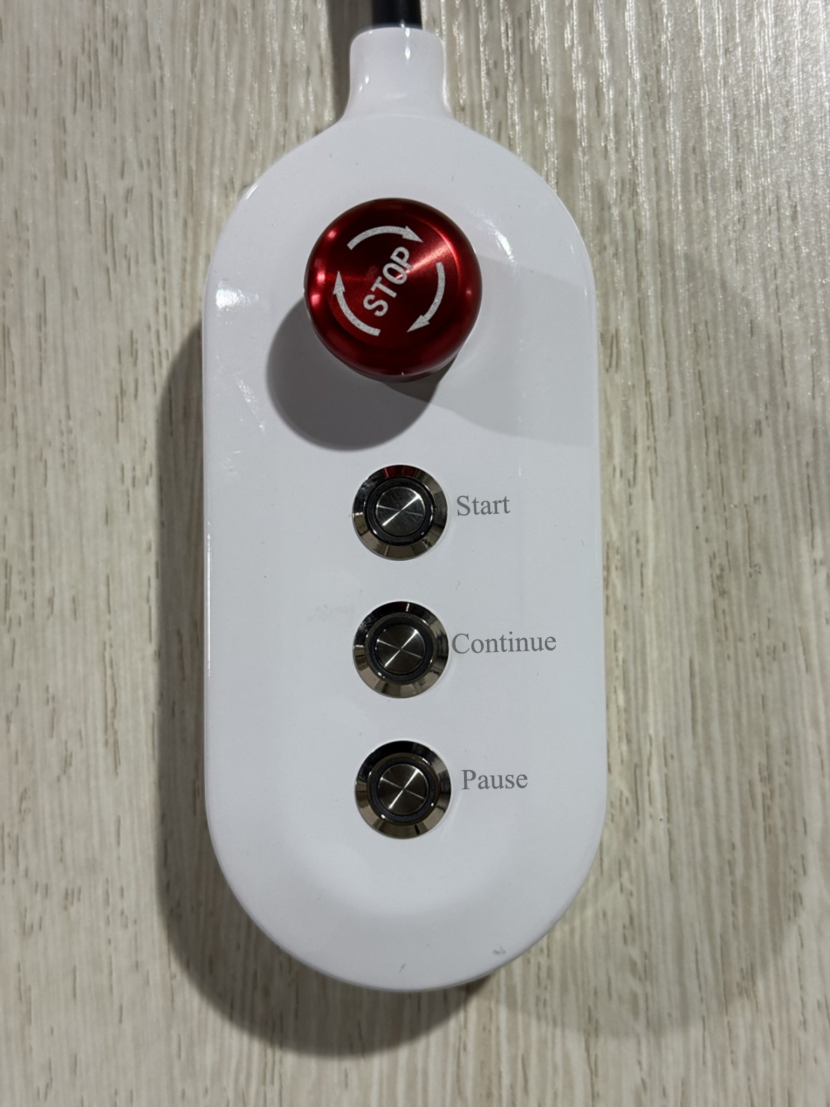
The appearance of the emergency stop button box is shown in the figure below, including four function buttons: emergency stop, start, continue and pause to control the motion program of the robotic arm.
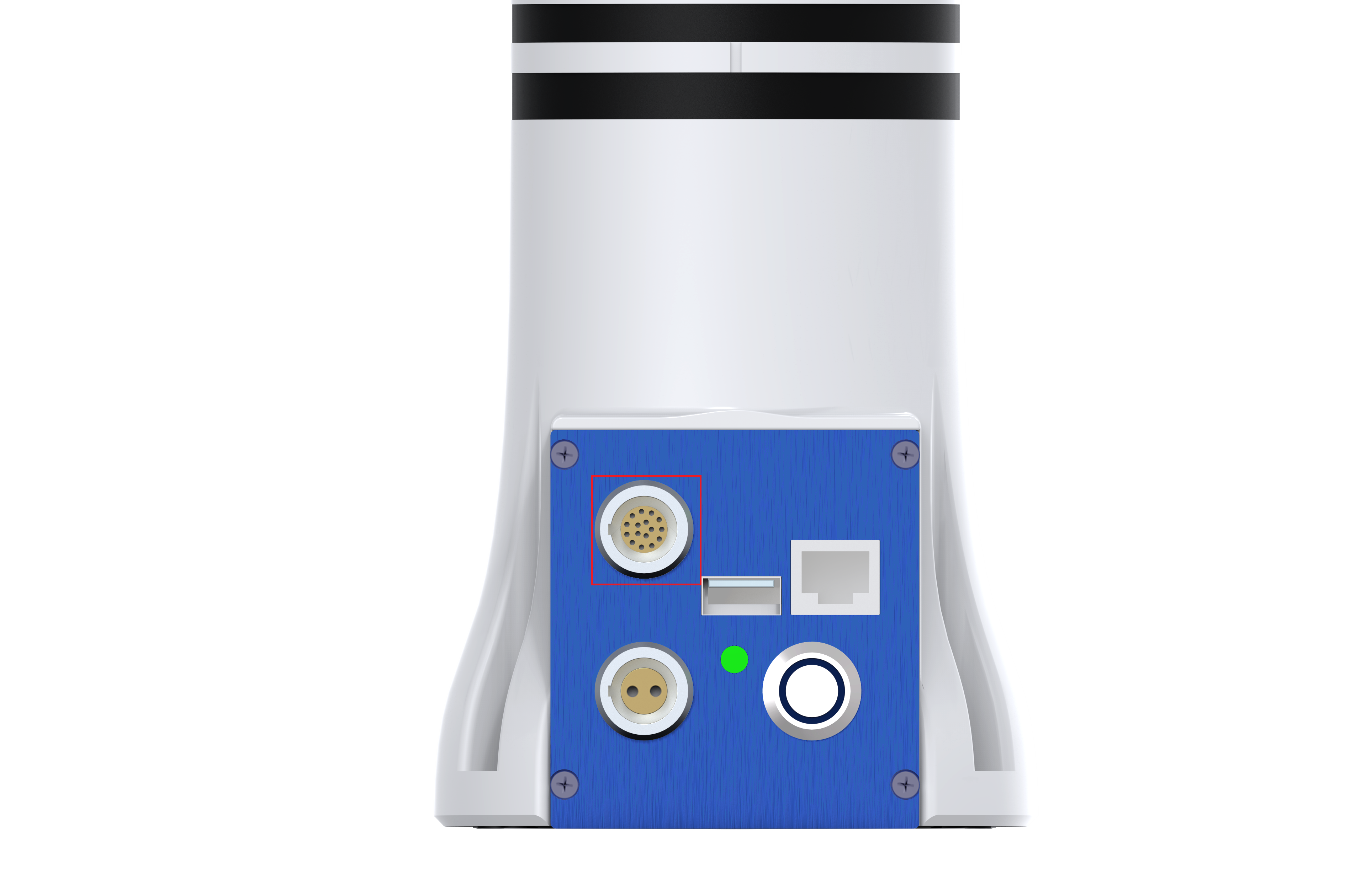
The button box is connected to the robotic arm through a 16-core wire and communicates based on IO multiplexing. The 16-core wire interface on the robotic arm is located behind the base, as shown in the figure below:
WARNING
- Cables are divided into first-generation cables and second-generation cables. You need to pay attention when wiring. For detailed information, please refer to the 16-core aviation plug cable of the fourth-generation controller or the 16-core aviation plug cable of the third-generation controller .
- When connecting the line, it is forbidden to plug and unplug the aviation plug with power on. When inserting the aviation plug, please be sure to check whether the pin is normal and ensure that the pin is aligned with the hole.
Wiring
Strip off one end of the 16-core aviation plug cable and connect it according to the following scheme (the second-generation cable sequence is used in this document):
- Emergency stop is divided into the following types according to different emergency stop modes:
- Circuit-type IO emergency stop: one end is connected to a white wire, and the other end is connected to gray/purple and blue wires.
- Emergency stop button multiplexed IO1: one end is connected to a black wire with white tracer, and the other end is connected to gray/purple and blue wires.
- Pause button multiplexed IO2: one end is connected to a white wire with red tracer, and the other end is connected to gray/purple and blue wires.
- Start button multiplexed IO3: one end is connected to a black wire with green tracer, and the other end is connected to gray/purple and blue wires.
- Continue button multiplexed IO4: one end is connected to a white wire with black tracer, and the other end is connected to gray/purple and blue wires. (There is a small amount of color exchange between wires of numbers 8 and 9, which needs to be distinguished by numbers)
- Emergency stop is divided into the following types according to different emergency stop modes:
Then refer to the circuit diagram to connect +24 V and GND, as shown in the figure below.
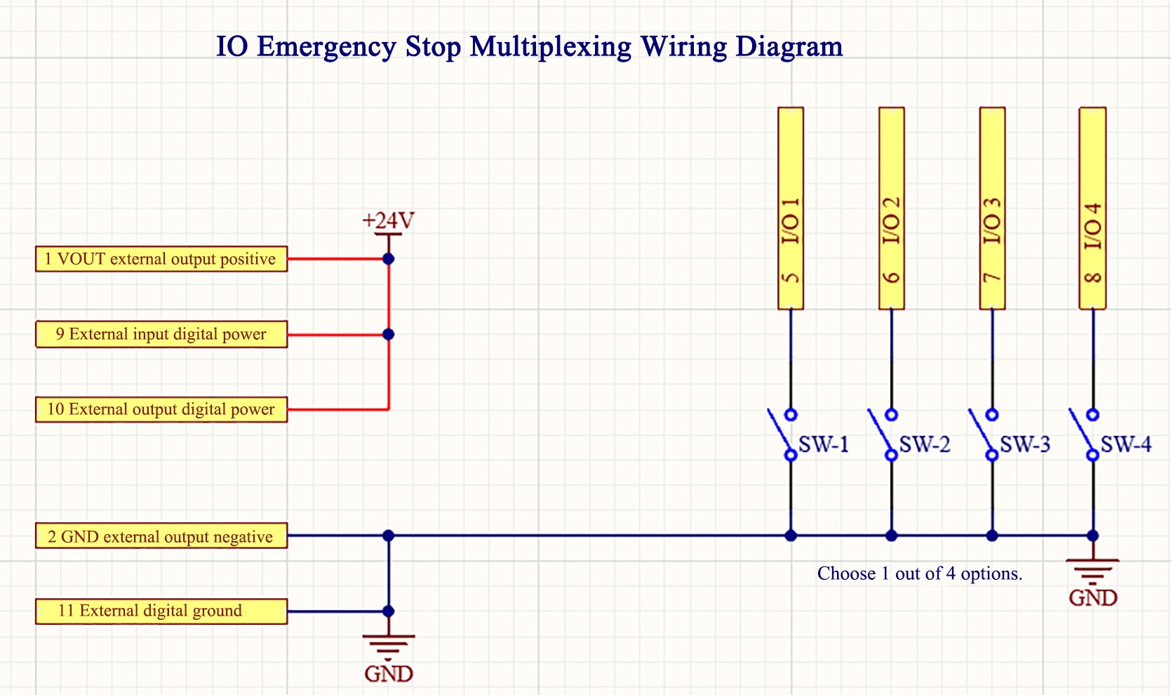
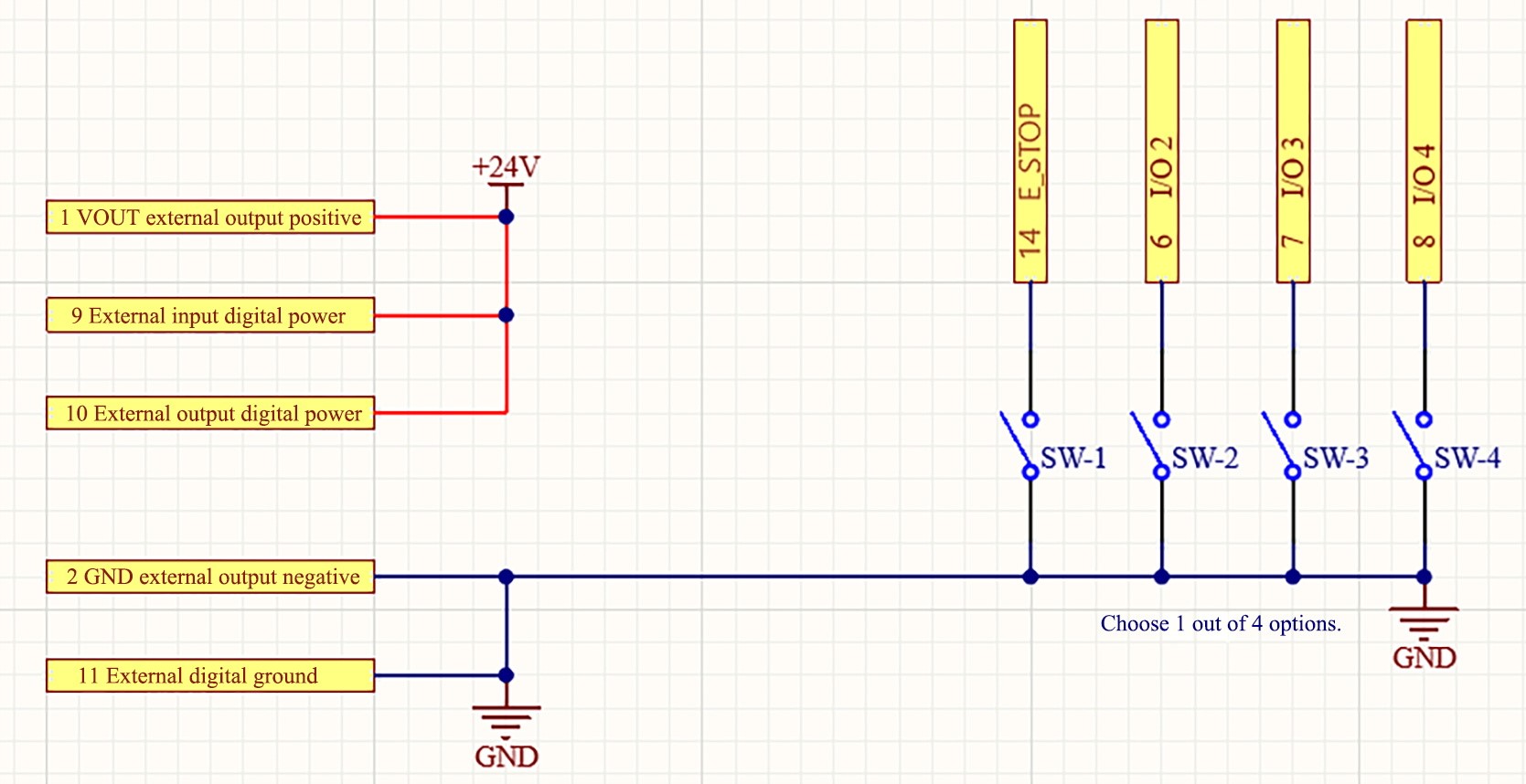
TIP
When wiring, it is necessary to follow the line sequence number. For example, the line sequence number 5 in the multiplexed IO emergency stop wiring diagram is for IO1, and the line sequence number 14 in the circuit-type IO emergency stop wiring diagram is for E_STOP.
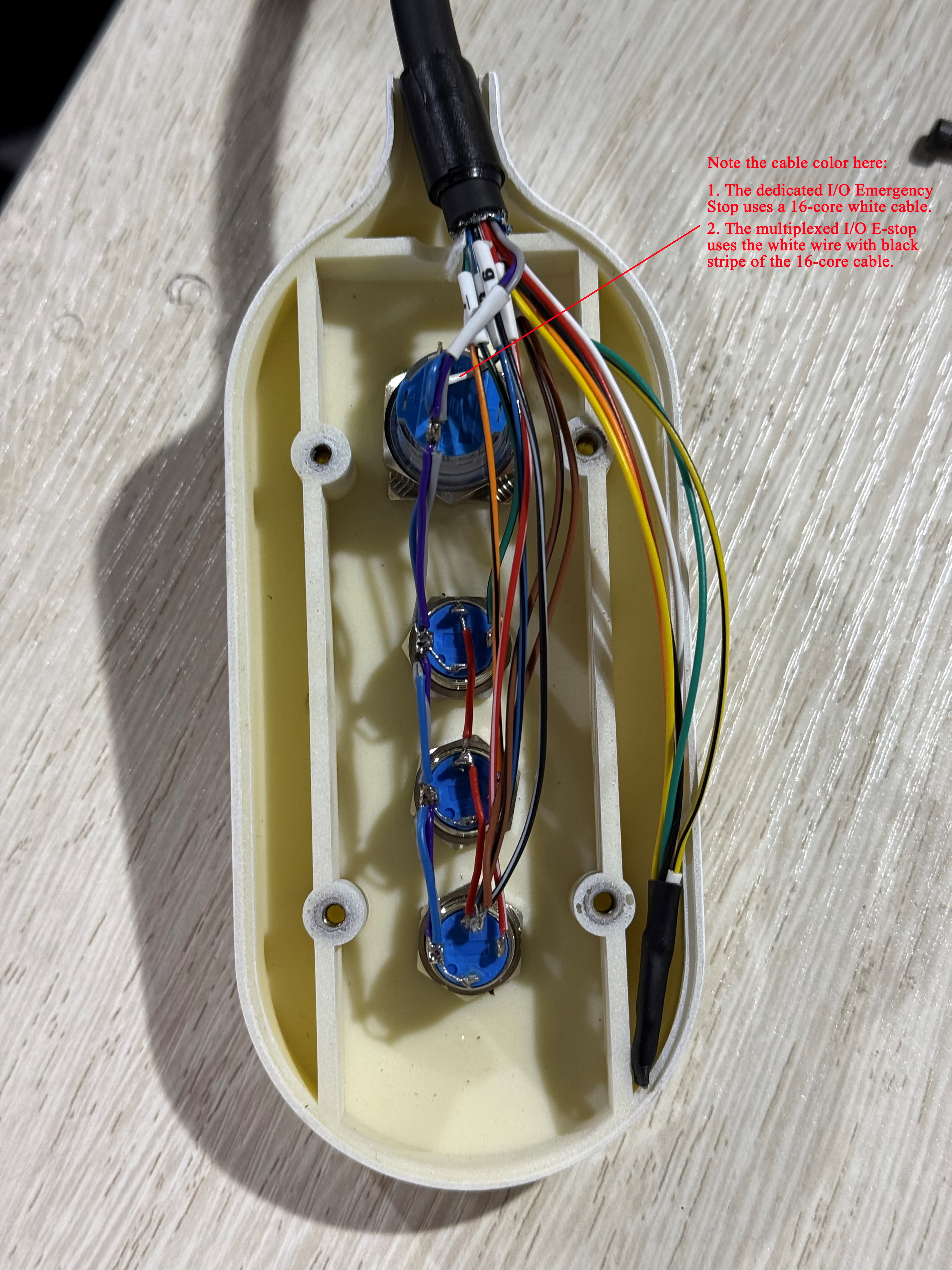
After the wiring is completed, it is shown in the figure below:
Button Box IO Configuration
After the button box wiring is completed, it is necessary to connect the robotic arm and open the Robotic Arm Teaching interface to configure it.
Access the Robotic Arm Teaching.
Select
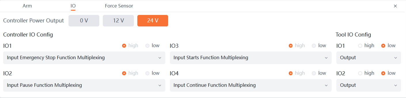
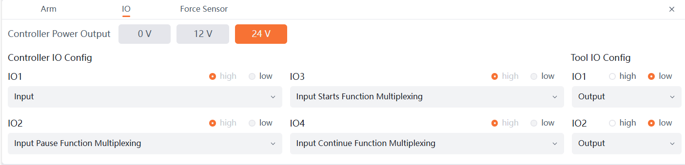
Statein the right menu bar and selectIOin the pop-up status page to enter the IO setting page.Set the controller power output to 24 V, and set IO1 (configured when using multiplexed IO emergency stop), IO2, IO3, and IO4 to Input Emergency Stop Function Multiplexing, Input Pause Function Multiplexing, Input Starts Function Multiplexing, and Input Continue Function Multiplexing respectively, as shown in the figure below. They can be used after the settings are completed.
TIP
It can be configured according to the actual emergency stop box wiring.