Power Bleeding Module
Product Overview
Product Positioning
The HPD power bleeding module is specifically designed for HPD joint modules to handle regenerative braking energy under high-load and high-speed operating conditions. This module effectively absorbs feedback energy, preventing excessive bus voltage caused by regenerative energy feedback and avoiding unexpected shutdowns triggered by overvoltage protection, thereby ensuring stable operation of the joint modules.
Application Scenarios
For robotic arm and robot manufacturers—especially in applications where low-voltage dexterous hands or other precision end-effectors are integrated—it is necessary to configure a power bleeding module when building systems with high-torque, high-voltage joint modules. This helps prevent damage or burnout of the joints themselves or attached components such as dexterous hands.
When using HPD 48V high-torque joint modules, such as the WHG and WHJ series, it is recommended to pair them with this power bleeding module.
Technical Information
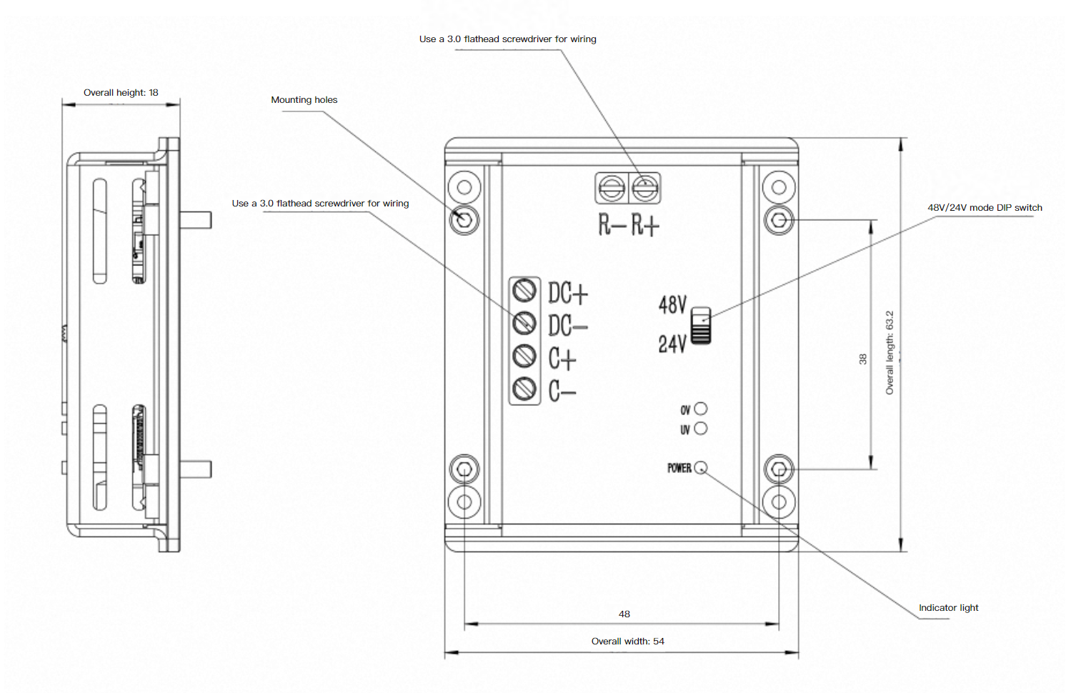
Physical Specifications
| Feature | Value | Description |
|---|---|---|
| Dimensions L*W*H (mm) | 63.2×54×18 | These specifications refer to the braking resistor integrated with the bleeding module, which is sufficient for WHG and WHJ 10/30/60 series joints under rated conditions. The power bleeding module requires no additional cooling measures when installed normally with natural convection. If used with WHG and WHJ 120/240/360 series joints, additional cooling measures are required. |
| Weight (g) | 66 |
Environmental Conditions
| Feature | Specification |
|---|---|
| Operating Temperature | 0°C to 50°C |
| Storage Temperature | -10°C to 60°C |
| Operating/Storage Humidity | 20% to 80% RH (non-condensing) |
Electrical Interface
The electrical interface of the power bleeding module is shown in the figure below:

The electrical interface definitions of the power bleeding module are shown in the table below:
| Terminal Mark | Terminal Function | Terminal Specification |
|---|---|---|
| DC+ | Connect to 24V/48VDC power supply positive | Wire Gauge: 26-14AWG Tool: Flat-head 3.0mm screwdriver |
| DC- | Connect to 24V/48VDC power supply negative | |
| R+ | Connect to resistor | |
| R- | ||
| C+ | Connect to capacitor | |
| C- |
Interaction Description
The interaction indicators of the power bleeding module are shown in the figure below:
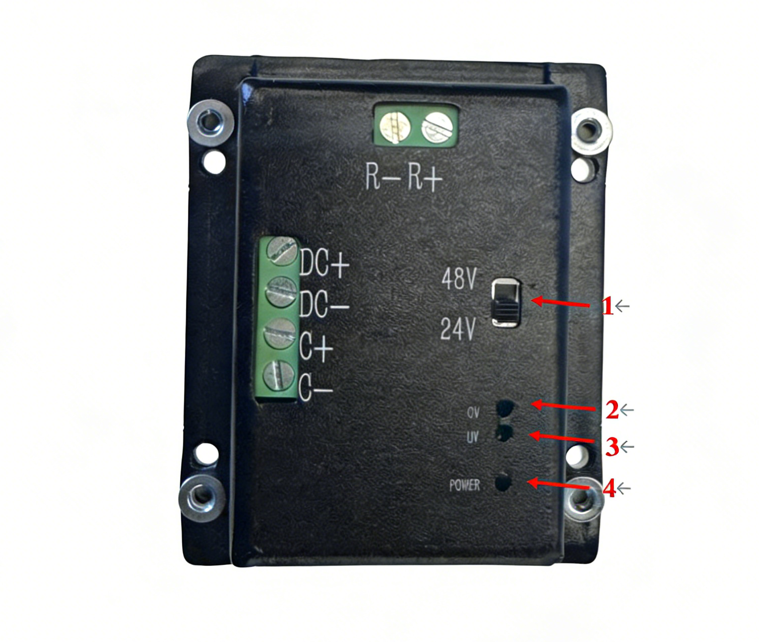
The detailed interaction definitions of the power bleeding module are shown in the table below:
| No. | Item Name | Status Description |
|---|---|---|
| 1 | Operating Voltage Selection | Manually select 48V or 24V operating mode. 48V joint modules require the 48V mode. |
| 2 | Overvoltage & Bleeding Indicator | See specific interaction modes below for details. |
| 3 | Undervoltage Indicator | |
| 4 | Power Indicator | Green light on: Module operating normally; Green light off: Module disconnected. |
TIP
The purpose of adding a bleeding resistor to the joint circuit is to dissipate excess energy through the resistor when the circuit is in the regenerative energy recovery phase, thereby preventing voltage spikes caused by energy feedback to the power supply.
The bleeding resistor must not be connected to the circuit for extended periods, as it will continuously generate heat, which may lead to component damage, circuit failure, and additional power consumption. Therefore, it is recommended to implement a reliable bleeding resistor control logic. For details, please refer to Interaction Mode in 48V Setting, Interaction Mode in 24V Setting, and Undervoltage Compensation Method.
Interaction Mode in 48V Setting
| Operating Status | Undervoltage | Normal | Bleeding | Overvoltage |
|---|---|---|---|---|
| Voltage Range | X ≤35V | 35V < X <52V | 52V≤ X <70V | 70V≤ X |
| Bleeding Mode | Off | Off | Activated | Off |
WARNING
Even if the voltage is lower than 35V, the motor will not stop rotating due to its wide operating voltage range and the system feedback mechanism.
When measuring the voltage thresholds of different discharge boards, there may be an error of 0.1–0.2V.
Interaction Mode in 24V Setting
| Operating Status | Undervoltage | Normal | Bleeding | Overvoltage |
|---|---|---|---|---|
| Voltage Range | X ≤15V | 15V < X <25.5V | 25.5V≤ X <33V | 33V≤ X |
| Bleeding Mode | Off | Off | Activated | Off |
Undervoltage Compensation Method
| Function Name | Parameters | Function Description |
|---|---|---|
| Undervoltage Compensation | 48V: 3 FTR20D560KJ Varistors, 1 80V/820µF Electrolytic Capacitor. | The 3 varistors and the electrolytic capacitor are all connected in parallel at the power supply terminals. Refer to: Recommended Accessory Specifications for Each Joint Model for specific quantities. |
| 24V: 3 FTR20D330KJ Varistors, 1 50V/820µF Electrolytic Capacitor. |
Recommended Accessory Specifications for Each Joint Model
The discharge module must be used together with capacitors and resistors. Different joint models require capacitors and resistors of different specifications and quantities, as shown in the table below:
WHJ10/30/60 and WHG1410E/1730E/2060E are equipped with one discharge box, one braking resistor (75W/5Ω), and one 820μF electrolytic capacitor (80V rating for 48V systems, 50V rating for 24V systems).
WHJ120 and WHG25120E/32240E are equipped with one discharge box, one braking resistor (300W/5Ω), and two 820μF electrolytic capacitors (80V rating for 48V systems, 50V rating for 24V systems).
| WHJ Series Joint Model | WHJ Series DC Power Supply Specification | WHG Series Joint Model | WHG Series DC Power Supply Specification | Braking Resistor Specification | Electrolytic Capacitor Specification | Number of Capacitors |
|---|---|---|---|---|---|---|
| WHJ10 | 63W, 48VDC | WHG1410E | 73W, 48VDC | 75W, 5Ω | 820uF, 80V | 1 |
| 63W, 24VDC | 73W, 24VDC | 75W, 5Ω | 820uF, 50V | 1 | ||
| WHJ30 | 137W, 48VDC | WHG1730E | 155W, 48VDC | 75W, 5Ω | 820uF, 80V | 1 |
| 137W, 24VDC | 155W, 24VDC | 75W, 5Ω | 820uF, 50V | 1 | ||
| WHJ60 | 258W, 48VDC | WHG2060E | 287W, 48VDC | 75W, 5Ω | 820uF, 80V | 1 |
| 258W, 24VDC | 287W, 24VDC | 75W, 5Ω | 820uF, 50V | 1 | ||
| WHJ120 | 720W, 48VDC | WHG25120E | 611W, 48VDC | 300W, 5Ω | 820uF, 80V | 2 |
| 720W, 24VDC | 611W, 24VDC | 300W, 5Ω | 820uF, 50V | 2 | ||
| / | WHG32240E | 873W, 48VDC | 300W, 5Ω | 820uF, 80V | 2 | |
| 873W, 24VDC | 300W, 5Ω | 820uF, 50V | 2 | |||
Wiring and Usage Instructions
The wiring diagram of the power supply, discharge module, and joint module is shown in the figure below:
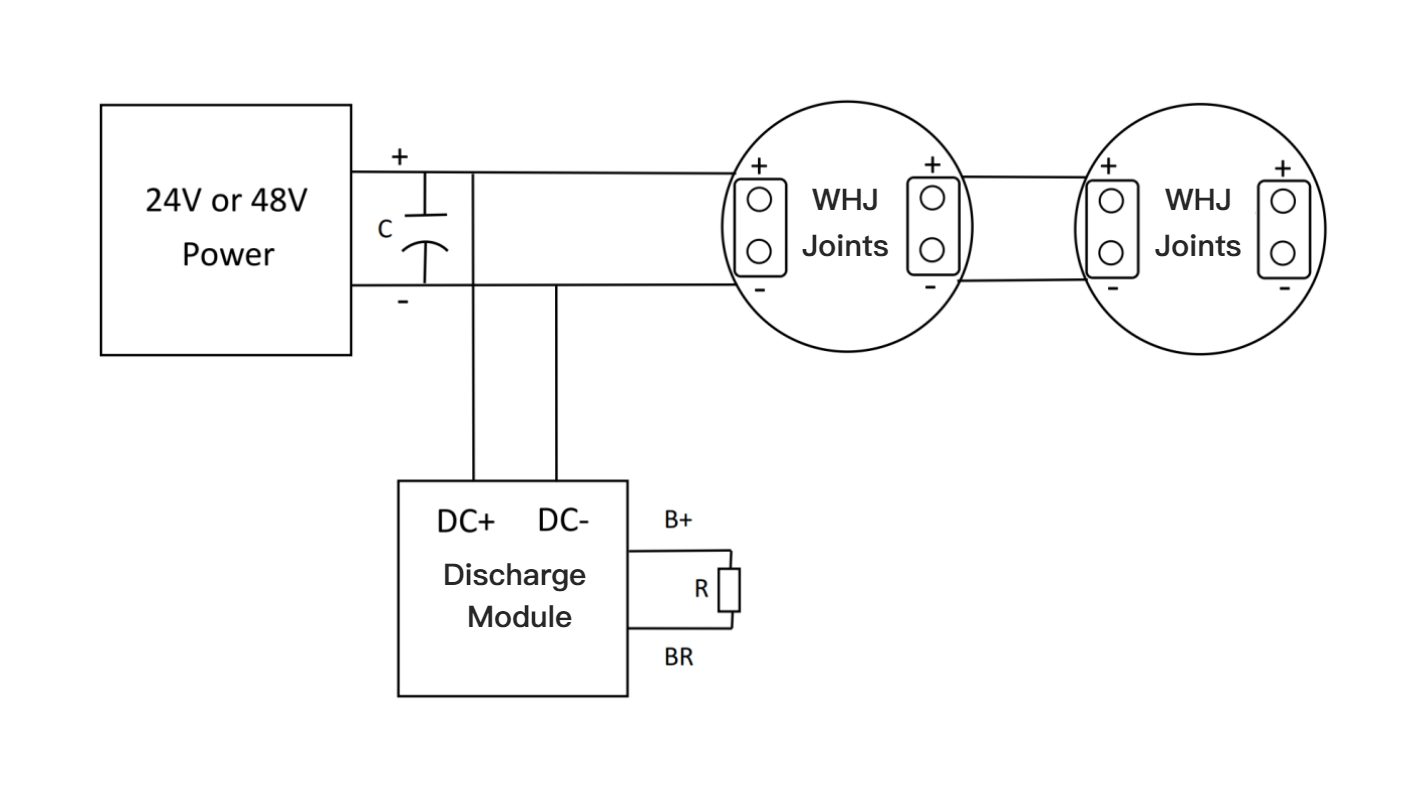

The wiring instructions for the discharge module are shown in the table below:
| No. | Item Name | Description |
|---|---|---|
| 1 | Power Supply | Connect the positive terminal to DC+ of the discharge module, and the negative terminal to DC- |
| 2 | Discharge Module | / |
| 3 | Discharge Module Resistor | Connect to R+ and R- terminals |
| 4 | Capacitor | Connect to C+ and C- terminals |
| 5 | Joint | Connected in parallel with the discharge module |
TIP
The discharge module and the joint are connected in parallel. According to the rated voltage of the joint, manually switch the voltage mode to either 48V or 24V. Connect the power supply positive terminal to the DC+ terminal of the discharge module, and the negative terminal to DC-. Connect the matching braking resistor to the R+ and R- terminals, and the capacitor to the C+ and C- terminals (if multiple capacitors are required, connect them in parallel). During wiring, strictly observe polarity and securely fasten all terminals.
Outline and Installation
Outline Dimensions
Installation Method
Note
The power bleeding module will generate heat during operation, and the resistor may become hot. Do not touch directly. The installation environment should have good ventilation and heat dissipation conditions, such as mounting on a large metal plate or inside an electrical cabinet with cooling fans.
