Getting Started:
Use Case Export Target Speed Sine Wave
Preparation
Software: Download and install WHJoint on your computer.
Hardware: CAN box, 24V power supply, joint.
Connecting the Joint to the Software
Reminder
Before connecting the software, first complete the hardware connection: Open WHJoint; connect the USB port of the CAN box to the computer, and the other end to the CAN interface of the joint (a 120Ω resistor must be connected between CANH and CANL); connect the joint to a 24V switching power supply.
Enter the software configuration page and select the Main page tab.
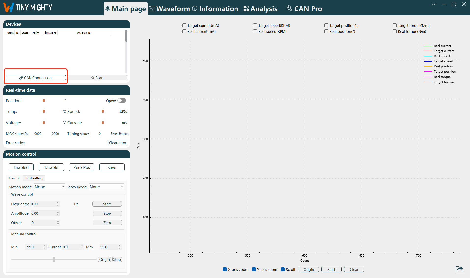
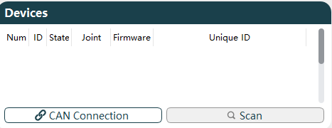
Click CAN Connection in the Devices module at the top left of the page.
Open the Set the Parameters window, configure the relevant parameter information, and click Confirm after configuration.
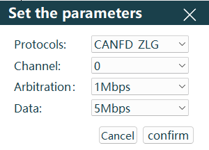
Select the Protocols column according to the CAN card you are using. Detailed descriptions are as follows:
Protocol Description CANFD_ZLG For Zhou Ligong brand CANFD protocol. CANOPEN_ZLG For Zhou Ligong brand CANOPEN protocol. CANFD_HK For Hongke brand CANFD protocol. CANOPEN_HK For Hongke brand CANOPEN protocol. Select 0 for the Channel column.
Select 1Mbps for the Arbitration column (currently, the joint arbitration field only supports 1Mbps).
Select 5Mbps for the Data column (currently, the joint data field only supports 5Mbps).
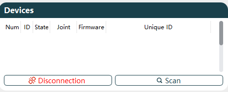
Confirm the connection status: Check the Device module. If Disconnection appears in the lower left instead of CAN Connection, it indicates that the CAN card is successfully connected to the computer.
Power on the joint.
Click Scan, and the information of the connected joint will appear in the Devices module.
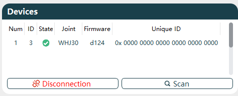
The joint information in the figure is as follows:
- Num: Device serial number. When multiple joints are connected, the serial number increases with the number of joints.
- ID: Joint ID, showing the set joint ID number according to real-time scanning.
- State: Enable status, showing the current joint enable status according to real-time scanning, and displayed in different colors based on the joint status.
Disabled Enabled 

- Joint: Shows the current joint model according to real-time scanning.
- Firmware: Shows the current joint firmware version model according to real-time scanning.
- Unique ID: Shows the unique ID of the current joint according to real-time scanning, which cannot be changed after leaving the factory.
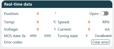
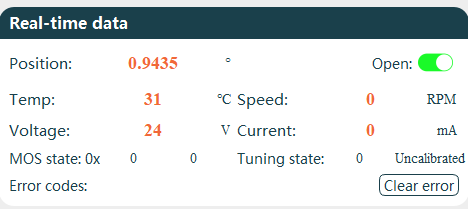
Enable Real-time Data Button
After the joint is successfully connected, you need to turn on the Real-time Data button to view the real-time data information of the joint.
| Serial Number | Name |
|---|---|
| 1 | Current angular position of the joint. |
| 2 | Enable/disable real-time data display of the joint. |
| 3 | Current internal temperature of the joint (must not exceed 90℃). |
| 4 | Current speed of the joint. |
| 5 | Current detected voltage of the joint. |
| 6 | Current loss current of the joint. |
| 7 | Current MOS tube status of the joint. |
| 8 | Current setting and calibration status of the joint. |
| 9 | Current error status display of the joint. |
| 10 | Clear the current error status. |
Configure Motion Information
Note
Before sine wave and square wave motion, be sure to set the limits, otherwise the joint target position over-limit alarm will occur.
Limit Setting: In the Motion Control module, click Limit Setting and configure the limit parameter information.
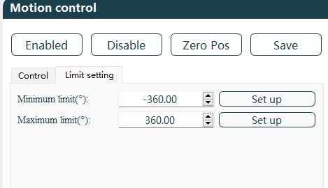
- Configure Minimum Limit and Maximum Limit: ±360 is for reference only, and should be set according to the actual application scenario of the joint. The minimum limit can be set to -214748°, and the maximum limit can be set to 214748°.
- After configuration, click Save.
Motion Control: In the Motion Control module, click Control and configure the motion parameter information.
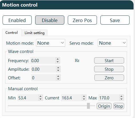
- Motion Mode: Set to sine wave.
- Servo Mode: Configure as needed, taking target speed as an example.
- Wave Control: The joint speed, angle size, etc., can be controlled by configuring parameters such as frequency, amplitude, and offset. Configuration example with speed servo and sine wave motion mode:
- Set the frequency to 0.2Hz, so the period of one sine wave motion is 20S.
- Set the amplitude to 20, corresponding to the sine wave amplitude.
- Set the offset to 100, so the equilibrium position angle of the sine wave deviates from y=0° by 100°.
- After setting, click Start, and the joint will start rotating back and forth; click Stop to stop the joint.
View and Export Waveforms
After configuring according to the above operations, you can view the corresponding waveform graph.
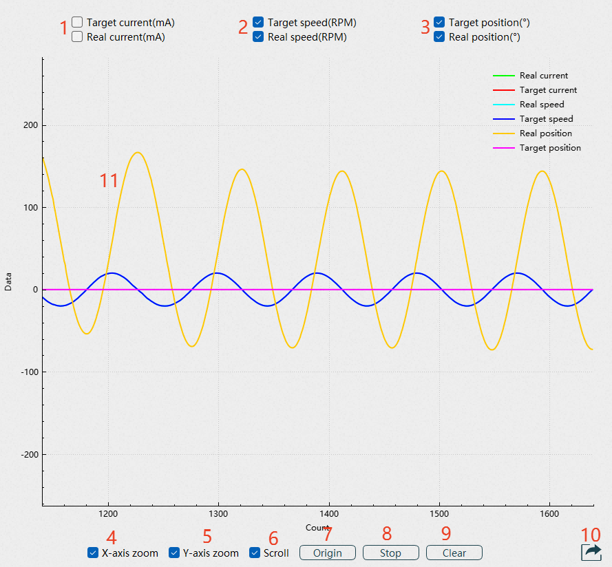
Serial Number Name 1 Current waveform display selection box. 2 Speed waveform display selection box. 3 Position waveform display selection box. 4 X-axis adjustment alone. 5 Y-axis adjustment alone. 6 Scroll display. 7 Waveform origin. 8 Waveform start/pause. 9 Clear waveform. 10 Data export. 11 Waveform display. When you need to view the relevant speed waveform, check the corresponding option and click Start, and the waveform will be displayed in the frame.
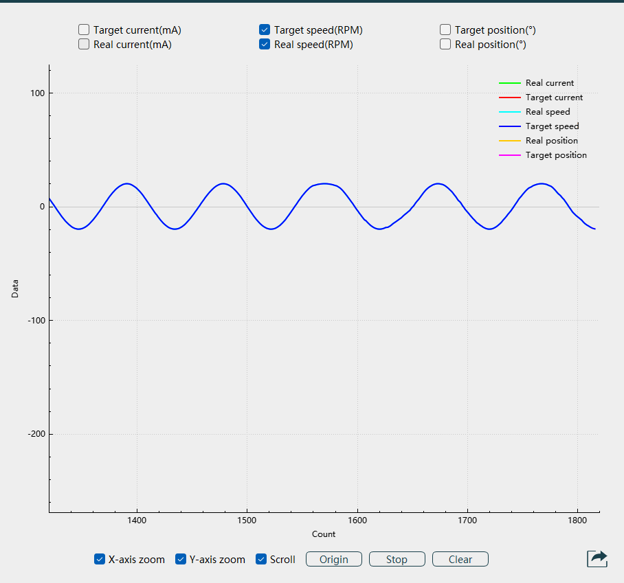
In the information box of the graph, the X-axis is the number of current points, and Y is the target value. Hover the mouse over the waveform to display the fuzzy coordinates of the current point.
Data export: Click the export button at the bottom right of the page, and select the Export type and Target as needed.
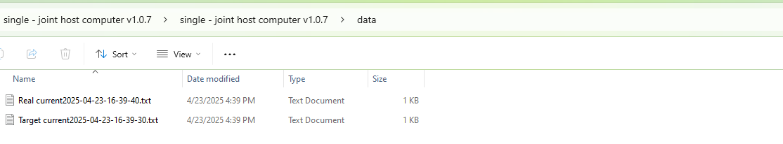
- Document export: The file name and file address cannot be selected. A prompt File written successfully will appear when exporting. The default file format is fixed as txt, and the file path is in the data folder of the upper computer.
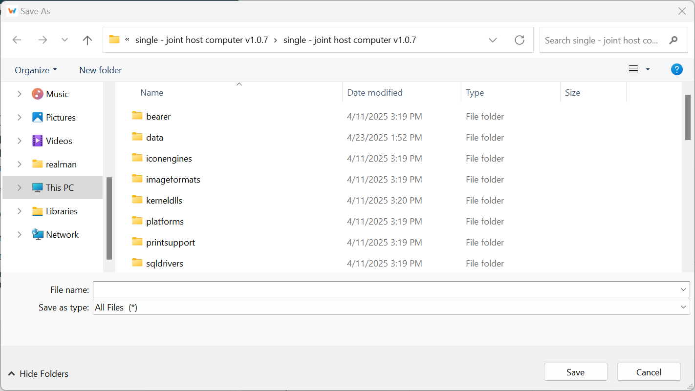
- Image export: You can select the file storage address and file name, and the default image format is png.
Update the Firmware
Preparation
Software: Download and install WHJoint on your computer.
Hardware: CAN box, 24V power supply, joint.
Connecting the Joint to the Software
Reminder
Before connecting the software, first complete the hardware connection: Open WHJoint; connect the USB port of the CAN box to the computer, and the other end to the CAN interface of the joint (a 120Ω resistor must be connected between CANH and CANL); connect the joint to a 24V switching power supply.
Enter the software configuration page and select the Main page tab.
Click CAN Connection in the Devices module at the top left of the page.
Open the Set the Parameters window, configure the relevant parameter information, and click Confirm after configuration.
Select the Protocols column according to the CAN card you are using. Detailed descriptions are as follows:
Protocol Description CANFD_ZLG For Zhou Ligong brand CANFD protocol. CANOPEN_ZLG For Zhou Ligong brand CANOPEN protocol. CANFD_HK For Hongke brand CANFD protocol. CANOPEN_HK For Hongke brand CANOPEN protocol. Select 0 for the Channel column.
Select 1Mbps for the Arbitration column (currently, the joint arbitration field only supports 1Mbps).
Select 5Mbps for the Data column (currently, the joint data field only supports 5Mbps).
Confirm the connection status: Check the Device module. If Disconnection appears in the lower left instead of CAN Connection, it indicates that the CAN card is successfully connected to the computer.
Power on the joint.
Click Scan, and the information of the connected joint will appear in the Devices module.
The joint information in the figure is as follows:
- Num: Device serial number. When multiple joints are connected, the serial number increases with the number of joints.
- ID: Joint ID, showing the set joint ID number according to real-time scanning.
- State: Enable status, showing the current joint enable status according to real-time scanning, and displayed in different colors based on the joint status.
Disabled Enabled - Joint: Shows the current joint model according to real-time scanning.
- Firmware: Shows the current joint firmware version model according to real-time scanning.
- Unique ID: Shows the unique ID of the current joint according to real-time scanning, which cannot be changed after leaving the factory.
Update Joint Firmware
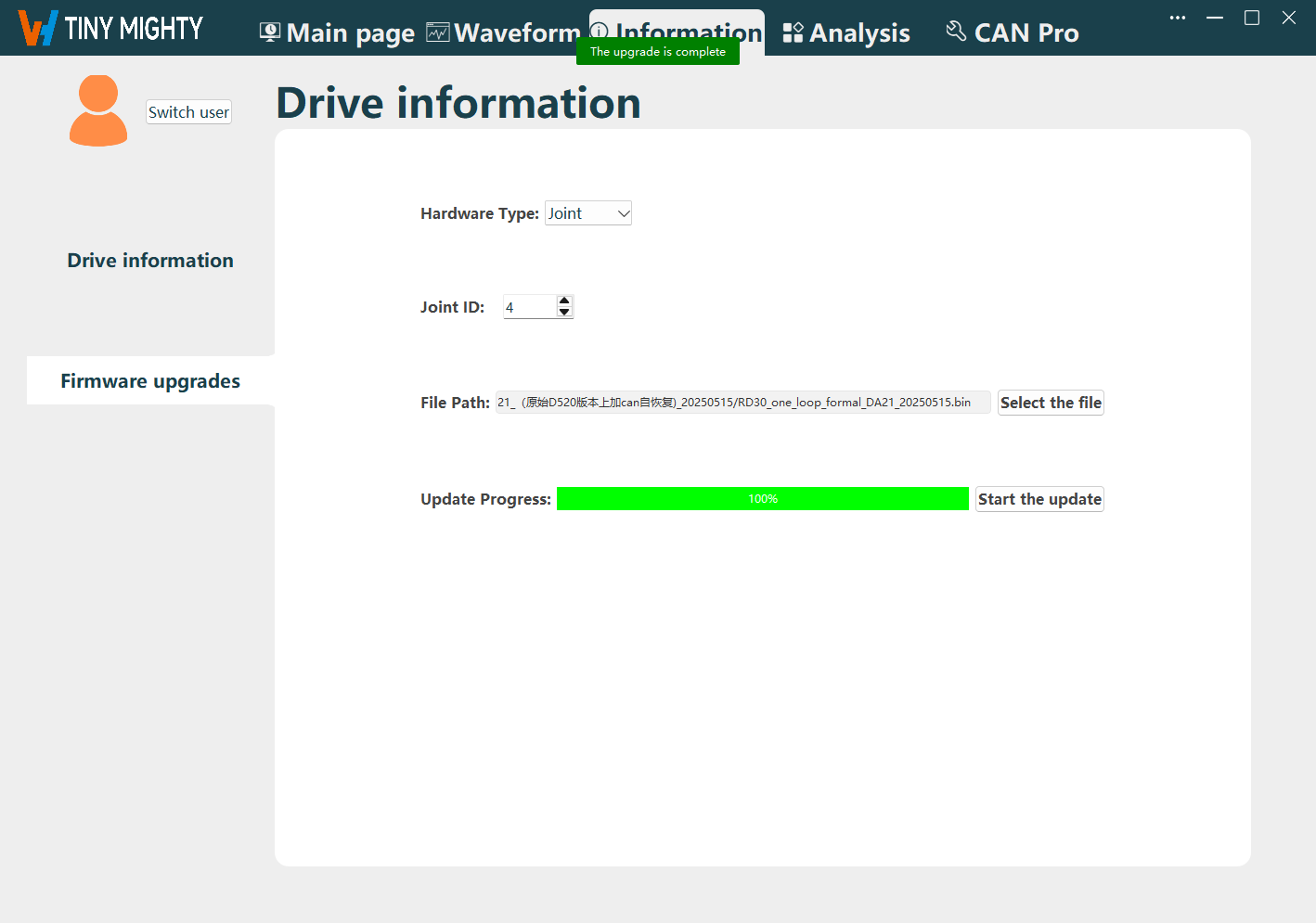
Enter the software configuration page and select the Information tab.
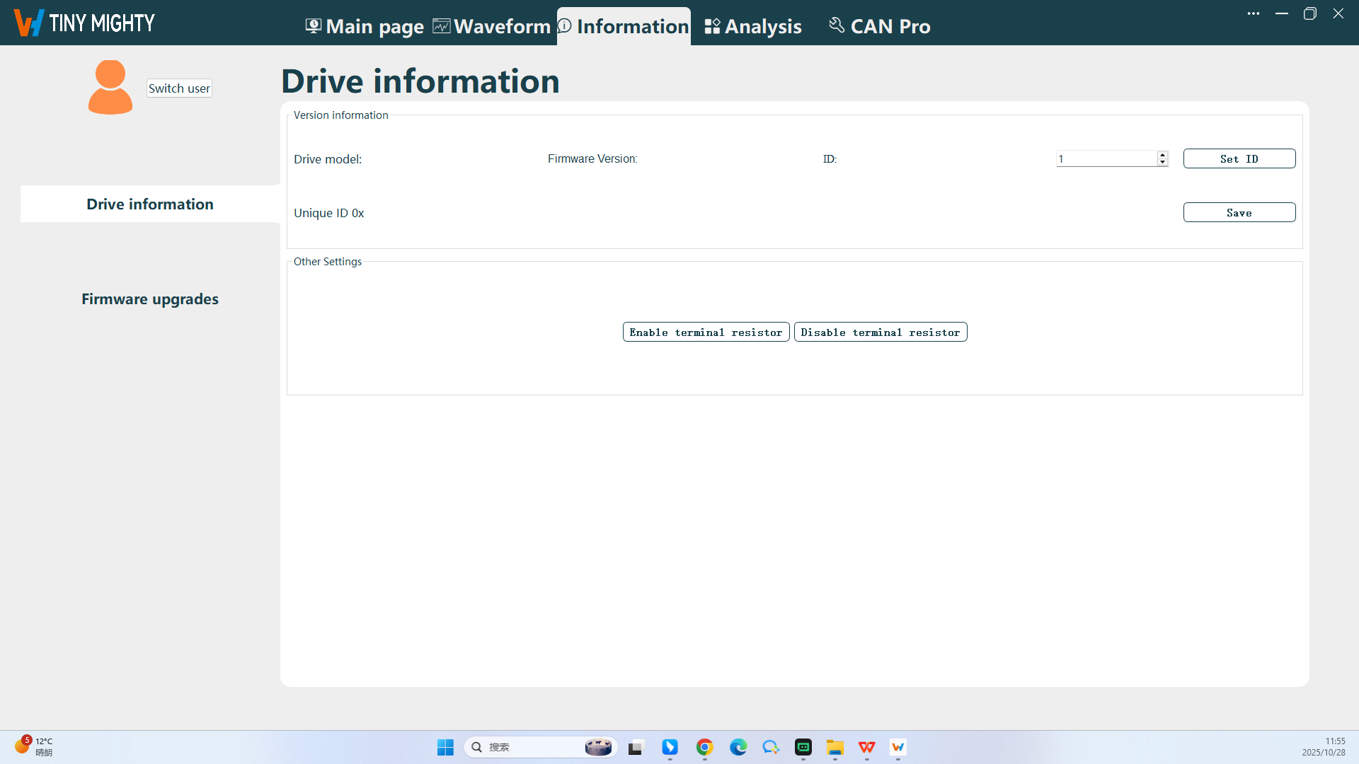
Click the Firmware Upgrades button on the left to enter the Firmware Upgrades page.
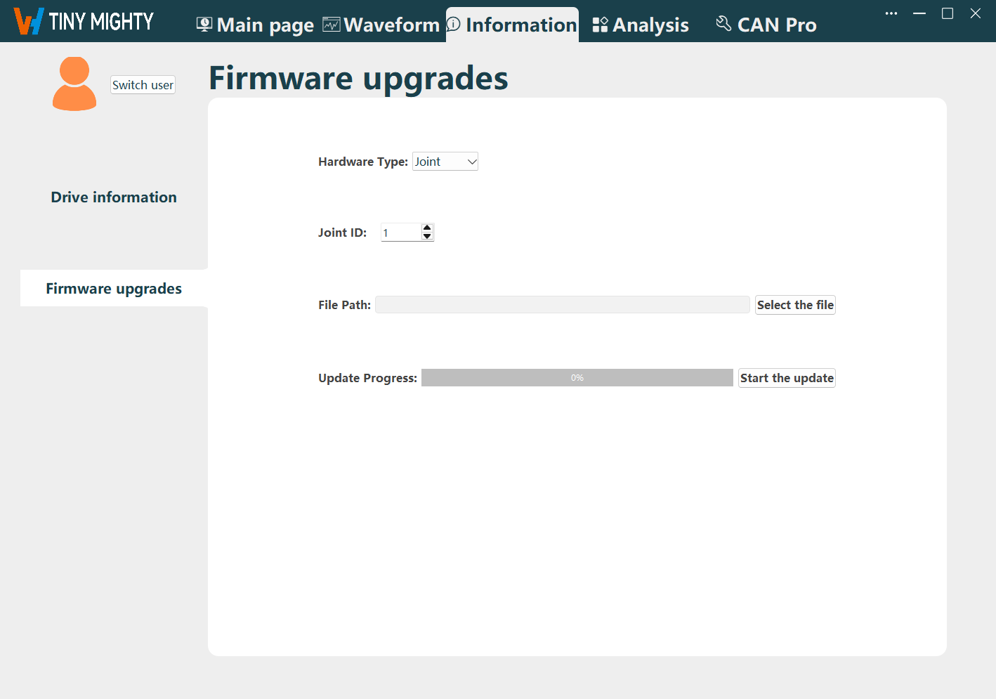
Customize the Joint ID and File Path information as needed.
- Joint ID: Select the joint ID displayed after the joint is connected to the software.
- File Path: Select the target update file.
Click Start the update.
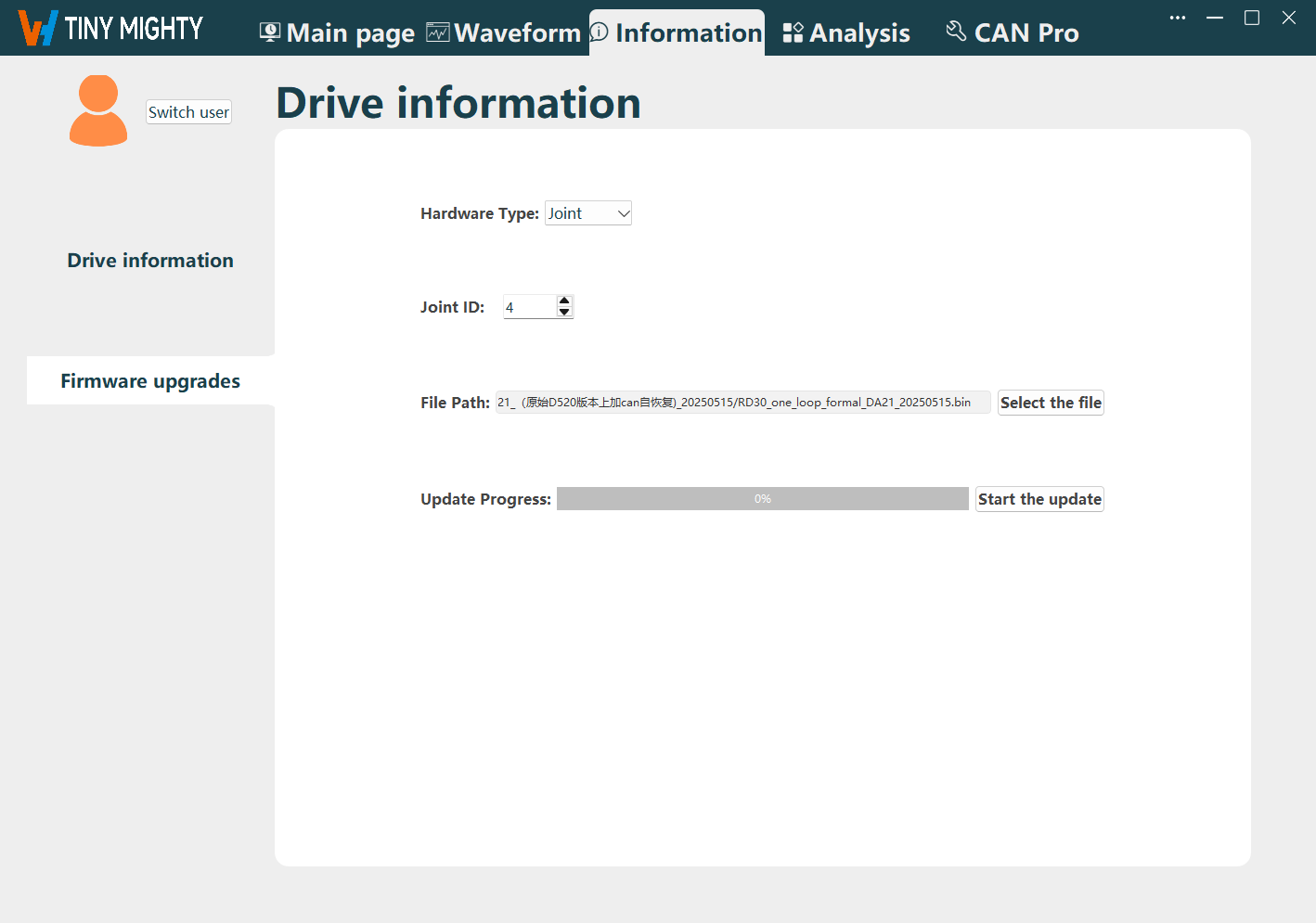
When the progress bar reaches 100%, the update is successful.