
SDK developer guide:
Hand-eye Calibration Overview
The hand-eye calibration is usually used in the field of robot and computer vision, especially in the scene where the interaction between the robotic arm and the environment needs to be accurately controlled. It is intended to unify the frames of the end effector (two-finger gripper, etc.) of the robotic arm and the camera for the coordinate transformation relationship between the camera and the robotic arm so that the robotic arm can accurately grasp the target positioned by the camera.
The hand-eye system is the relationship between the hand (robotic arm) and the eye (camera). When the eye (camera) sees an object, it has to tell the hand (robotic arm) the position of the object. After the position of the object in the eye (camera) is determined, if the relationship between the eye (camera) and the hand (robotic arm) is established, the position of the object in the hand (robotic arm) is available.
The hand-eye calibration is required in multiple scenes such as robot grasping objects, dynamic environment interaction, precision measurement and detection, and visual servo control.
After hand-eye calibration, no recalibration is necessary unless the relative position of the camera and the robotic arm changes. The following calibration methods apply to upright, side, and flip mounting.
Two types of hand-eye calibration:
Type 1: The eye (camera) is fixed in a hand (robotic arm)
Eye-in-hand system: The camera, mounted at the end of the robotic arm, moves with the robotic arm.

Type 2: The eye (camera) is fixed outside the hand (robotic arm)
Eye-to-hand system: The camera is mounted outside the robotic arm.

Principle
1. Eye-in-hand
For the eye-in-hand situation, the robot hand-eye calibration is to calibrate the coordinate transformation relationship between the camera and the end of the robotic arm:

In the process of transforming the three-dimensional coordinates of the target point, the first problem is the position change relationship between frames of the end and the camera, that is, the hand-eye position relationship and the result of hand-eye calibration. The relationship is represented by the symbol X and solved by the equation AX=XB. Where A represents the transformation relationship of the end in two adjacent movements; and B represents the relative motion of camera frame in two adjacent movements.
As shown in the figure above, it is the eye-in-hand. (It is for illustration purposes only, rather than a real experimental scene.) Fixed at the end of the robotic arm, the camera moves with the robotic arm.

A: Refers to the pose of the end in the robotic arm frame, which is obtained through the robotic arm API (known).
B: Refers to the pose of the camera in the end frame. The transformation is fixed, and if it is known, the actual position of the camera is available at any time, so it is necessary (unknown, to be computed).
C: Refers to the pose of the calibration board in the camera frame, which is obtained through
solvePnPfrom the checkerboard corner points and the camera intrinsics.D: Refers to the pose of the calibration board in the base frame. In the calibration process, if only the end of the robotic arm is moving, and the calibration board and base is not moving, the pose relationship is fixed.
Therefore, if B is obtained, the pose D of the calibration board in the robotic arm frame is available.
As shown in the figure below, move the robotic arm to two positions, ensure that the calibration board is seen under both positions, then construct the space transformation loop:

Then we can obtain the following equations:
It is a typical equation AX=XB, and by definition, where X is a 4×4 homogeneous transformation matrix:
The purpose of hand-eye calibration is to compute X.
2. Eye-to-hand

During eye-to-hand calibration, fix the base and camera, and mount the calibration board at the end of the robotic arm, so the relationship between the calibration board and the end and between the camera and the base remains unchanged.
Calibration target:
Frame transformation matrix from camera to base
Method:
- Mount the calibration board at the end of the robotic arm.
- Move the end of the robotic arm and use the camera to take n images (10−20) of the calibration board under different robotic arm poses.
Each time the image and robotic arm pose are collected, the following equation is met:
Where,
| Symbol | Description |
|---|---|
| Transformation matrix from the calibration board to the end (the calibration board is fixed at the end of the robotic arm during the calibration, so the transformation matrix from the calibration board to the end remains unchanged) | |
| Use the end pose to obtain | |
| Use the hand-eye calibration to obtain | |
| Use the camera calibration to obtain |
Finally, the following equations are obtained:
It is also a typical equation AX=XB, and by definition, where X is a 4×4 homogeneous transformation matrix, R is the rotation matrix from camera to base frame, and t is the translation vector from camera to base frame:
The purpose of hand-eye calibration is to compute X.
Key code interpretation
Code access
Get the latest code in github link.
Code directory
├── eye_hand_data  # Collected data and calibration results of each batch
├── libs
│   ├── auxiliary.py  # Auxiliary packages for the program
│   ├── log_settings.py  # Log packages
│   └── calibration.py  # Solver and quality check shared by both calibration methods
├── config.yaml  # Checkerboard parameters and error limits
├── collect_data.py  # Hand-eye calibration data collection program
├── compute_in_hand.py  # Eye-in-hand calibration computation program
├── compute_to_hand.py  # Eye-to-hand calibration computation program
├── requirements.txt  # Environment dependency file
├── save_poses.py  # Computation dependency file
└── save_poses2.py  # Computation dependency file
Data collection and computation
Run python collect_data.py in the project directory. When collection starts, the script switches the controller work coordinate system to Base. Keep the same tool coordinate system during the calibration. Click the Capture_Video preview window and press s after the robotic arm comes to a stop. The script uses the current frame and then queries the end pose of the robotic arm. Press q or Esc in the preview window to exit. The preview is enlarged twice, while the saved images keep the capture resolution.
Each batch of data is saved under eye_hand_data in the program directory, containing the numbered images, poses.txt, and camera.json. The images correspond to the poses line by line in numerical order; do not delete individual images, delete pose lines, or modify the image numbering. Samples that fail to communicate or save are not counted.
camera.json saves the current color stream resolution, the intrinsics, and the distortion parameters. These parameters are used during computation to obtain the calibration board pose through solvePnP. For legacy data without this file, calibrateCamera is still used to estimate the intrinsics from the images of the current batch, and a prompt is displayed. Do not copy the intrinsics of another camera or another resolution into the data directory.
Choose the solver script according to the mounting method, and specify the corresponding collection directory. The two mounting methods are collected separately. When the directory is omitted, the script selects the latest batch by directory name.
| Mounting method | Command | Output |
|---|---|---|
| Eye-in-hand | python compute_in_hand.py "eye_hand_data/<eye-in-hand batch directory>" | result_in_hand.json, camera to end |
| Eye-to-hand | python compute_to_hand.py "eye_hand_data/<eye-to-hand batch directory>" | result_to_hand.json, camera to base |
The solver uses the current config.yaml. Check the checkerboard parameters of the batch before recomputing an old batch; recomputing overwrites the result file of the same name in that batch directory.
The program reads the images by actual file name. When corner detection or the image quality check fails, the corresponding robotic arm pose is removed as well. At least 6 valid pairs are required; 15 to 20 groups are recommended, with sufficient rotation about different axes.
The computation logic is shared by libs/calibration.py. Eye-in-hand uses the end-to-base pose, while eye-to-hand uses its inverse transformation. Each line of poses.txt records x,y,z,rx,ry,rz, in meters and radians. Here the end refers to the current tool coordinate system used for the collected poses.
The result is saved as result_in_hand.json or result_to_hand.json in the data of the current batch, recording the matrix, the transformation direction, the units, the valid image numbers, the removed images and their reasons, the reprojection error, and the fixed-relation error. The quaternion order is [x,y,z,w], and the translation unit is meters.
After the computation, the terminal displays the RMS, the maximum, and the corresponding limits of the position residual (millimeters), the orientation residual (degrees), and the reprojection error (pixels). The residual summary is also saved in the quality field of the result file. When a limit is exceeded, the same values are printed and the result is still marked as rejected.
The current config.yaml uses a reprojection RMS limit of 2 px for a single image, and the images exceeding the limit are removed together with the corresponding poses. The limit of the maximum position residual of the fixed relation is 12 mm, and the limit of the maximum orientation residual is 3°. If either of the latter two exceeds the limit, the result is marked as rejected. If the solver fails ahead of time, it is marked as failed; if it passes the check, it is marked as candidate. (Note: the limit only means that the computed residual is too large, so the result is not recommended for use. The possible reasons include insufficient rotation angle, poses that are difficult to satisfy for precise computation, the accuracy and the state of the arm, and so on.)
The camera fixed-intrinsics path supports OpenCV Brown distortion parameters and images without distortion; other RealSense distortion models with non-zero coefficients are explicitly rejected, and their coefficients cannot be used directly as Brown parameters.
Hand-eye calibration computation
R, t = cv2.calibrateHandEye(
    R_tool, t_tool, rvecs, tvecs, method=cv2.CALIB_HAND_EYE_TSAI
)
Use the
calibrateHandEyefunction of OpenCV for hand-eye calibration.In compute_in_hand.py, compute the rotation matrix R_cam2end and the translation vector T_cam2end of the camera against the end.
Cvoid cv::calibrateHandEye(InputArrayOfArrays R_end2base, InputArrayOfArrays T_end2base, InputArrayOfArrays R_board2cam, InputArrayOfArrays T_board2cam, OutputArray R_cam2end, OutputArray T_cam2end, HandEyeCalibrationMethod method = CALIB_HAND_EYE_TSAI)In compute_to_hand.py, compute the rotation matrix R_cam2base and the translation vector T_cam2base of the camera against the base.
Cvoid cv::calibrateHandEye(InputArrayOfArrays R_base2end InputArrayOfArrays T_base2end InputArrayOfArrays R_board2cam InputArrayOfArrays T_board2cam OutputArray R_cam2base OutputArray T_cam2base HandEyeCalibrationMethod method = CALIB_HAND_EYE_TSAI)
Adopt the
CALIB_HAND_EYE_TSAI, which is a common hand-eye calibration algorithm.
save_poses.py Key code interpretation
1. Define a function that converts Euler angles into the rotation matrix
def euler_angles_to_rotation_matrix(rx, ry, rz):
    # Compute the rotation matrix
    Rx = np.array([[1, 0, 0],
                   [0, np.cos(rx), -np.sin(rx)],
                   [0, np.sin(rx), np.cos(rx)]])

    Ry = np.array([[np.cos(ry), 0, np.sin(ry)],
                   [0, 1, 0],
                   [-np.sin(ry), 0, np.cos(ry)]])

    Rz = np.array([[np.cos(rz), -np.sin(rz), 0],
                   [np.sin(rz), np.cos(rz), 0],
                   [0, 0, 1]])

    R = Rz @ Ry @ Rx

return R- Define a function that converts Euler angles (rotations around axes X, Y, and Z) into the rotation matrix.
- The Euler angles are expressed in radians. The rotation matrix is
Rz @ Ry @ Rx, which is applied from right to left when acting on column vectors.
2. Convert the pose to a homogeneous transformation matrix
def pose_to_homogeneous_matrix(pose):
    x, y, z, rx, ry, rz = pose
    R = euler_angles_to_rotation_matrix(rx, ry, rz)
    t = np.array([x, y, z]).reshape(3, 1)

    H = np.eye(4)
    H[:3, :3] = R
    H[:3, 3] = t[:, 0]

return H- Convert the pose (position and orientation) into a 4×4 homogeneous transformation matrix for matrix operations.
- Take the position
(x, y, z)as the translation vector and the orientation(rx, ry, rz)as the rotational Euler angles. - Use the resulting homogeneous transformation matrix
Hto indicate the rotation transformation of the end against the base.
The solver reads the poses directly from poses.txt and writes the calibration matrix into the result JSON.
Calibration procedure
1. Environmental requirements
Python environment preparation
Python 3.11 is recommended. The currently pinned RealSense Python package provides Python 3.11 installers for Linux and Windows x86-64. See requirements.txt and RealSense release files for the dependency versions.
Ubuntu:
python3.11 -m venv .venv
source .venv/bin/activate
python -m pip install -r requirements.txt
Windows PowerShell:
py -3.11 -m venv .venv
.\.venv\Scripts\Activate.ps1
python -m pip install -r requirements.txt
Equipment preparation
Robotic arm: RM75 RM65 RM63 GEN72
Camera: Intel RealSense D435; the collection script requests the color stream at
640 × 480 @ 30 FPSSpecial data cable for camera
Network cable
Calibration board (1 or 2)
Print a paper calibration board.
L is about 27.72mm when printed on A4 paper (use the actual length for the computation):

Another one is about 20.21mm when printed on A4 paper (use the actual length for the computation):
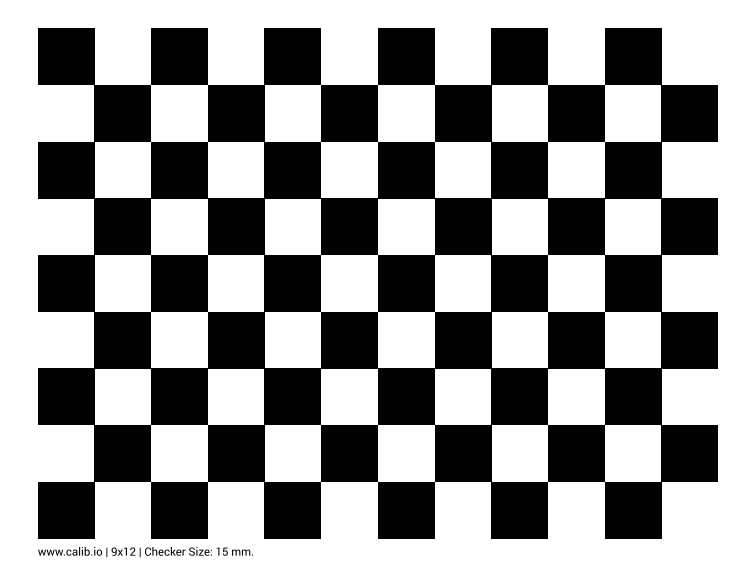
Search "calibration board checkerboard" and buy on Taobao.
2. Calibration procedure
Parameter configuration
Fill in the actual checkerboard parameters in the checkerboard_args section of the configuration file (config.yaml).
| Parameter | Description | Current configuration |
|---|---|---|
XX | Number of the horizontal inner corner points, one less than the number of the horizontal squares | 8 |
YY | Number of the vertical inner corner points, one less than the number of the vertical squares | 5 |
L | Measured side length of a single square, in meters | 0.02772 |
After printing, measure the total length of several consecutive squares and divide it by the number of squares. Print scaling changes the actual square length.

Eye-in-hand
Data collection
Use the camera cable to connect the computer and the D435 camera, and the network cable to connect the computer and the robotic arm.
Set the IP addresses of the computer and the robotic arm to the same network segment.
- If the IP address of the robotic arm is 192.168.1.18, set the IP address of the computer to network segment 1.

- If the IP address of the robotic arm is 192.168.10.18, set the IP address of the computer to the corresponding network segment (see settings above). The script probes
192.168.1.18and192.168.10.18in turn and connects to the TCP port8080of the first reachable address.
- If the IP address of the robotic arm is 192.168.1.18, set the IP address of the computer to network segment 1.
Place the calibration board on the plane, fix the camera at the end of the robotic arm, and align the camera with the calibration board.
During the calibration, the calibration board is fixed in the working area of the robotic arm to ensure that it is observed by the camera installed at the end of the robotic arm from different angles. The exact position of the calibration board is unimportant because it is not necessary to know its pose against the base. However, the calibration board shall remain stationary during the calibration.
Run the script
collect_data.py, and a pop-up window will appear.Adjust the pose of the end of the robotic arm until the checkerboard in the camera view is clear and complete.
Note:
Keep the calibration board in the camera view at an angle with the camera mirror.

The following pose is wrong:

- Click the preview window and press
sto collect after the robotic arm comes to a stop. - Move the robotic arm 15−20 times, repeat steps 5 and 6, and collect about 15−20 images of the calibration board under different robotic arm poses.
Note:
Move the rotation axis of the robotic arm end for a rotation angle as large as possible (greater than 30°). Ensure enough rotation angle changes on all three axes (X, Y, Z). (Rotate around the Z-axis of the robotic arm end for multiple angles, take some images, and then rotate around the X-axis)

Calibration results
Select the collection directory of the eye-in-hand mounting method and run compute_in_hand.py to get the calibration results.
Get the rotation matrix and translation vector of the camera frame against the end frame.
Eye-to-hand
Data collection
Use the camera cable to connect the computer and the D435 camera, and the network cable to connect the computer and the robotic arm.
Set the IP addresses of the computer and the robotic arm to the same network segment.
- If the IP address of the robotic arm is
192.168.1.18, set the IP address of the computer to network segment 1. - If the IP address of the robotic arm is 192.168.10.18, set the IP address of the computer to network segment 10.
- If the IP address of the robotic arm is
Fix the calibration board (print a smaller paper board for easy fixing) at the end of the robotic arm, keep the camera stationary, and move the end of the robotic arm until the calibration board appears in the camera view.
During the calibration, the calibration board, mounted on the end effector of the robotic arm, moves with the robotic arm. It is either fixed directly on the flange or fixed by the fixture. The exact position is unimportant because it is unnecessary to know the relative pose of the calibration board and the end effector. Importantly, the calibration board must not shift relative to the flange or fixture during movement, so it must be fixed in place well or held tightly by the fixture. Mounting brackets made of rigid materials are recommended.
Run the script
collect_data.py, and a pop-up window will appear.Adjust the pose of the end of the robotic arm until the checkerboard in the camera view is clear and complete.
Note
Keep the calibration board in the camera view at an angle with the camera mirror.
Click the preview window and press
sto collect after the robotic arm comes to a stop.Move the robotic arm 15−20 times, repeat steps 5 and 6, and collect about 15−20 images of the calibration board under different robotic arm poses.
- Move the rotation axis of the robotic arm end for a rotation angle as large as possible (greater than 30°).
- Ensure enough rotation angle changes on all three axes (X, Y, Z).
Calibration results
Select the collection directory of the eye-to-hand mounting method and run compute_to_hand.py to get the calibration results.
Get the rotation matrix and translation vector of the camera frame against the base frame.
Note: The unit of the translation vector is meters.
Error range
candidate means that the consistency check of the same batch of samples has been passed. The actual positioning accuracy must be verified with independent measured points in the workspace, and the measured points should cover the distances and poses actually used.
Possible problems during calibration
When computing the collected data, i.e. when executing the following script:
python compute_in_hand.pyOr
python compute_to_hand.pyThe following problems may occur
Problem description: [ERROR:0@1.418] global calibration_handeye.cpp:335 calibrateHandEyeTsai Hand-eye calibration failed! Not enough informative motions--include larger rotations.
Causes: Insufficient rotation of the collected images, including larger rotations.
The hand-eye calibration requires the robot to perform motions in space to obtain an exact relationship between the camera and the end. If there is not enough rotation change in the robot's motions, especially larger rotation on each axis, the calibration algorithm cannot accurately compute the hand-eye relationship.
Solution:
- Increase rotations:
- During the data collection, keep the robot performing larger rotations. Ensure enough rotation angle changes on all three axes (X, Y, Z).
- For example, the rotation angle is better than 30°, because enough motion information is available.
- Diversify motion poses:
- During the data collection, ensure that the robot end performs various poses, including translation and rotation.
- Avoid moving only in a small area or on an axis.
- Increase the number of data collection:
- The solver requires at least 6 sets of samples that pass the check. It is recommended to collect 15 to 20 groups of poses under different orientations, leaving a margin for removal.
- Collect more data to improve the stability and accuracy of calibration.
Application of hand-eye calibration results
Below, T_target_source denotes the transformation from the source frame to the target frame. Both the 3D points and the object poses should lie in the camera optical frame used for the calibration, and the length unit is meters. Pixel coordinates need to be converted into 3D points by combining the depth and the camera intrinsics.
First, load the result JSON matching the mounting method. After verification with independent measured points, apply the matrix to the actual positioning.
import json
from pathlib import Path

import numpy as np

from save_poses import pose_to_homogeneous_matrix


def load_calibration(result_path, direction):
    result = json.loads(Path(result_path).read_text(encoding="utf-8"))
    if result["status"] != "candidate":
        raise ValueError("Please select a result that passes the quality check")
    if result["direction"] != direction:
        raise ValueError(f"The calibration direction should be {direction}")
    return np.asarray(result["matrix"], dtype=float)
Eye-in-hand
Theory
Start with the robotic arm without a camera. Its two main frames are as follows:
- Robotic arm base frame
- End effector frame

To pick up an object, the robotic arm needs to know the pose of the object against the base frame. Based on such information and the robot geometry, the joint angle at which the end effector/fixture moves toward the object is available.

The pose of the object against the camera frame is obtained through the model recognition. For the robotic arm to pick up the object, it is required to convert the object pose from the camera frame to the base frame.

In this case, the coordinate transformation is done indirectly:
The pose

If the object is a 3D point or pose in the camera frame, the following describes the mathematical transformation theory of the object from the camera frame to the base frame.
The pose of the robotic arm is represented by a homogeneous transformation matrix.
The following equation describes how to convert a single 3D point from the camera frame to the base frame:
The object pose is converted from the camera frame to the base frame.
The equation above gives the pose of the object in the base frame, T_base_object. If it is used to generate the grasping target, the transformation T_object_tcp of the TCP relative to the object at grasping time must be multiplied on the right, which contains the gripper orientation and the grasping offset.
T_base_tcp = T_base_object @ T_object_tcpBoth mounting methods use the same grasping transformation.
Code
Use the end pose end_pose = [x, y, z, rx, ry, rz] corresponding to the moment of the image, where the position is in meters, the orientation is in radians, and the work coordinate system is Base. Use the same tool coordinate system as the one used during the calibration.
def wrist_camera_to_base(result_path, end_pose):
    T_end_camera = load_calibration(result_path, "camera_to_end")
    T_base_end = pose_to_homogeneous_matrix(end_pose)
    return T_base_end @ T_end_camera
The object is a 3D point. Append
1to the camera point so that the matrix applies both the rotation and the translation.pythondef wrist_point_to_base(result_path, end_pose, camera_point): T_base_camera = wrist_camera_to_base(result_path, end_pose) return (T_base_camera @ np.append(camera_point, 1.0))[:3]The object has a complete pose. Pass the 4 × 4 transformation from the object to the camera and return the transformation from the object to the base.
pythondef wrist_object_to_base(result_path, end_pose, T_camera_object): T_base_camera = wrist_camera_to_base(result_path, end_pose) return T_base_camera @ T_camera_object
Eye-to-hand
Theory
The pose of the object in the camera frame is available by the camera through the model. The pose of the object against the robotic arm is obtained by multiplying the pose of the camera against the base frame by the pose of the object against the camera frame:
If the object is a 3D point or pose, the following describes the mathematical transformation theory of the object from the camera frame to the base frame.
The following equation describes how to convert a single 3D point from the camera frame to the base frame:
The object pose is converted from the camera frame to the base frame.
Code
For the fixed camera, use the camera-to-base transformation in result_to_hand.json directly. The relative position of the camera and the robotic arm base remains fixed.
The object is a 3D point.
pythondef fixed_point_to_base(result_path, camera_point): T_base_camera = load_calibration(result_path, "camera_to_base") return (T_base_camera @ np.append(camera_point, 1.0))[:3]The object has a complete pose.
pythondef fixed_object_to_base(result_path, T_camera_object): T_base_camera = load_calibration(result_path, "camera_to_base") return T_base_camera @ T_camera_object
If the downstream interface requires a 6D pose in the same format as poses.txt, the matrix can be split into the translation and the Euler angles. The xyz Euler angles here correspond to the Rz @ Ry @ Rx in save_poses.py.
from scipy.spatial.transform import Rotation


def matrix_to_pose(transform):
    xyz = transform[:3, 3]
    rpy = Rotation.from_matrix(transform[:3, :3]).as_euler("xyz")
    return np.concatenate((xyz, rpy))