

Robot Teaching Pendant:
Using the Teaching Pendant Teaching Pendant Portal
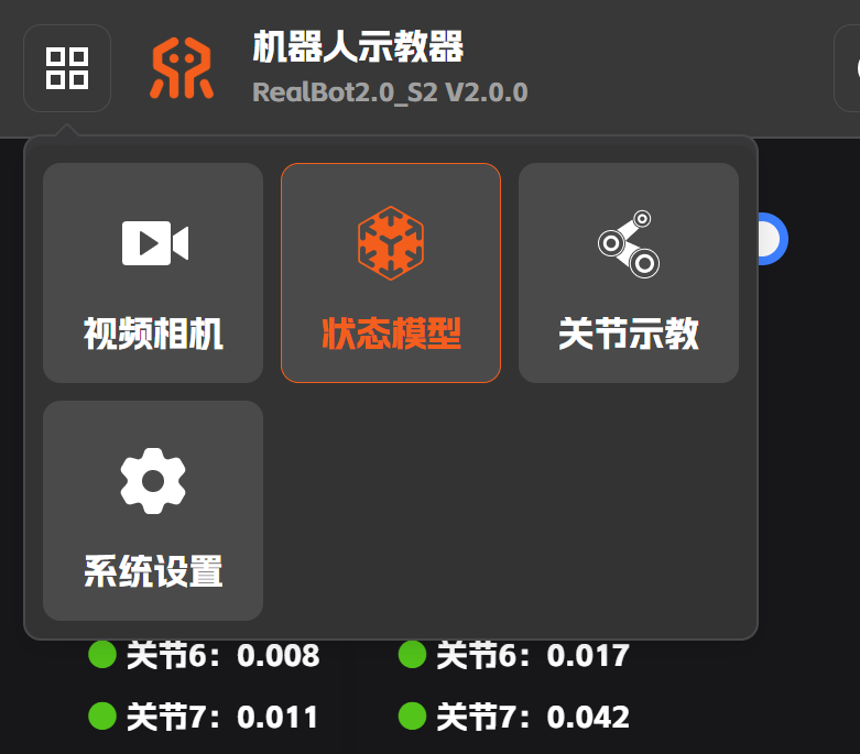
You can switch between function pages—such as Video Camera, State Model, Joint Teaching, and System Settings—via the menu icon at the upper left corner of the teaching pendant. The usage of each page after switching is described below.
Note
For the motion control buttons on the teaching pendant, a single tap produces only a small motion. To reach the target position, you need to hold the button down while observing the joint movement of the robot; the motion stops once the button is released.
When adjusting the robot's pose, make sure there are no people or obstacles around the robot to avoid accidents.
State Model
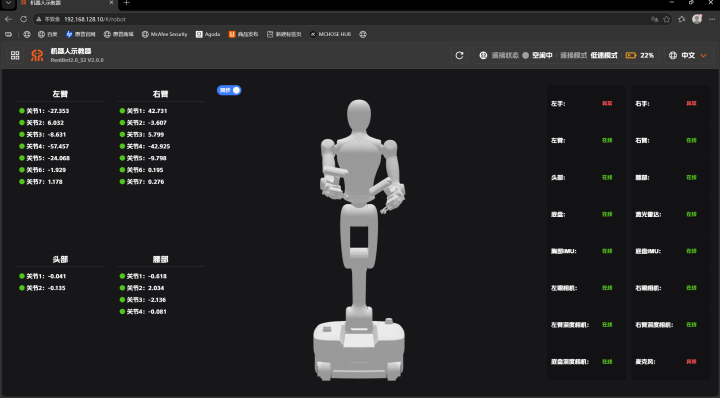
Switch to [State Model] via the menu icon at the upper left to view the current angles of the left arm, right arm, head, and waist, as well as the online status of each node of the robot.
Video Camera
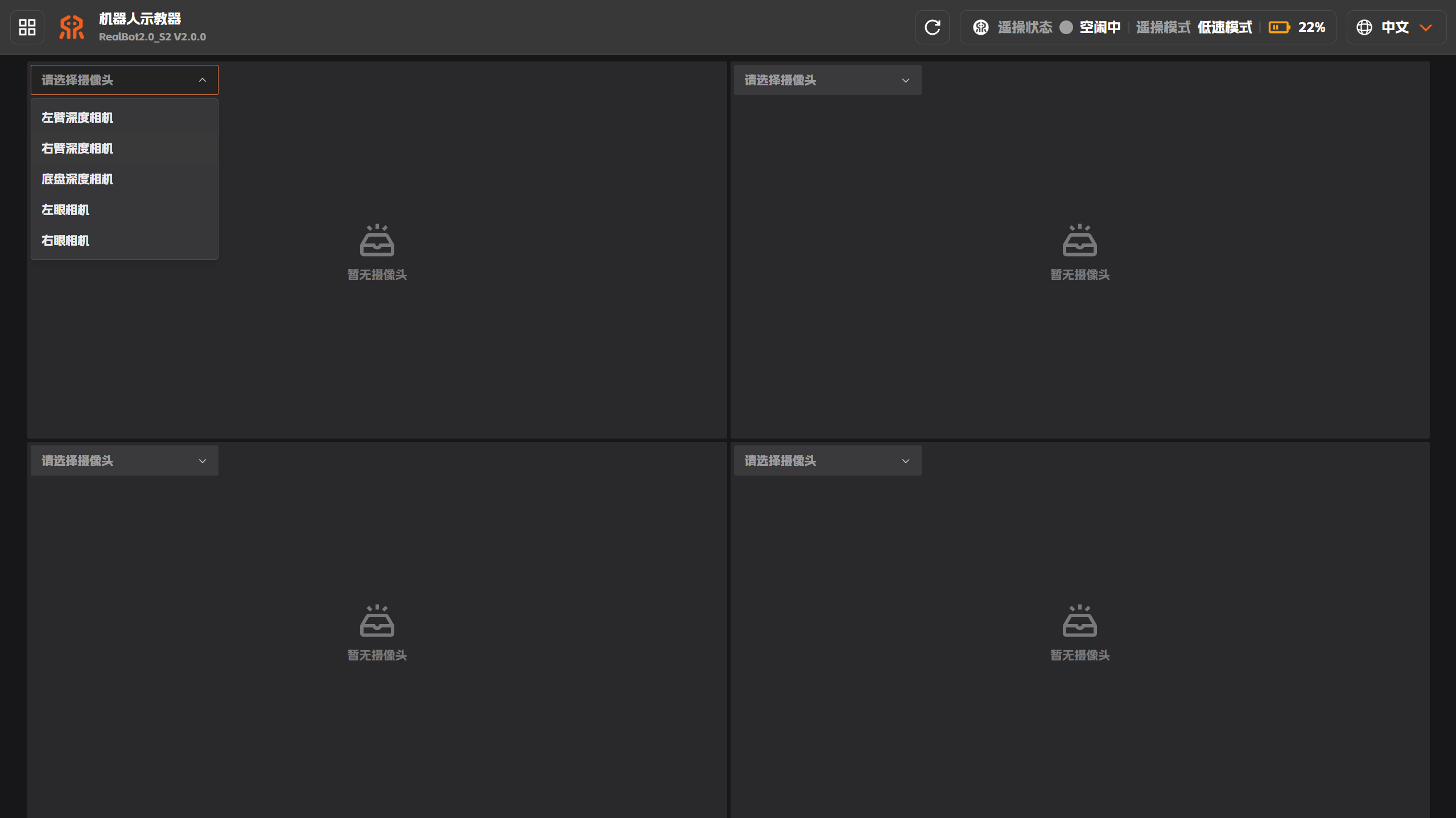
Switch to [Video Camera] via the menu icon at the upper left to switch and view the feeds of the left-arm depth camera, right-arm depth camera, chassis depth camera, left eye camera, right eye camera, etc., via the drop-down list of each area.
Joint Teaching
Switch to [Joint Teaching] via the menu icon at the upper left to view and adjust the current joint angles, and to pack the robot or restore the initial pose, etc.
Robot Packing
When the gripper and cameras are installed, pressing [One-Click Packing] is not recommended. Otherwise, the gripper may collide with the chassis while the waist descends during packing. Before transport packing, remove the gripper and cameras first, then perform the packing operation.
After removing the gripper and cameras, you can click [One-Click Packing] to pack, or press the [Pack] button in the joint area of the left arm, right arm, head, or waist to pack each part separately.
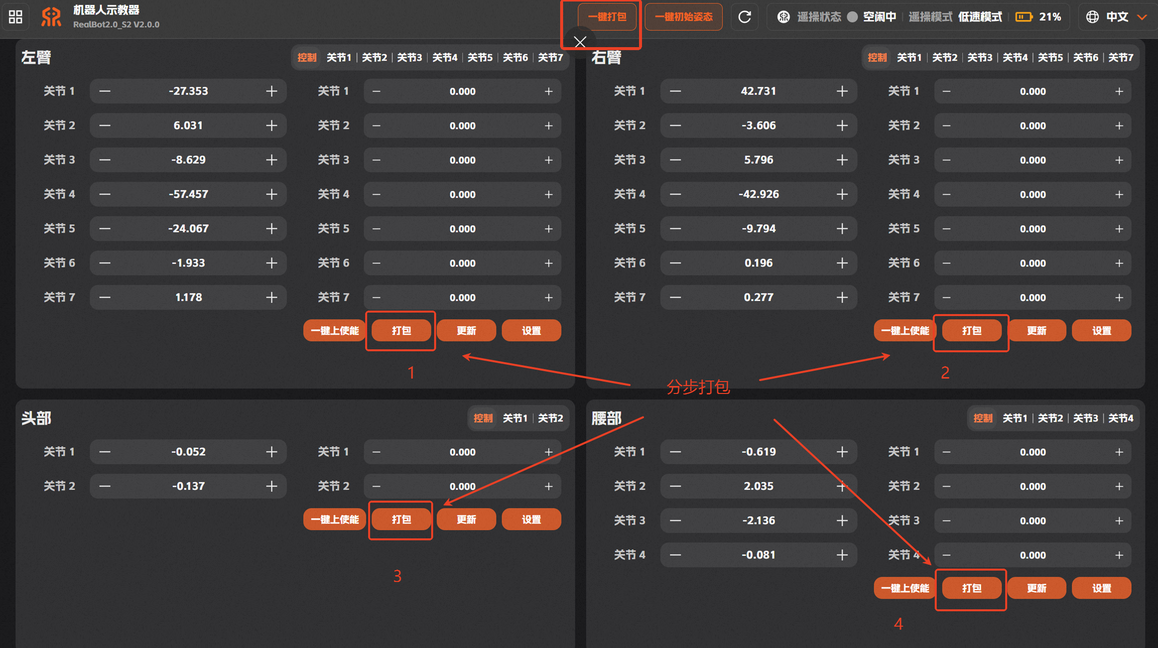
During one-click packing, to fit the height of the transport case, it is recommended to compare the height of the case with that of the waist after packing, and gradually fine-tune the waist pose to match the foam height of the case.
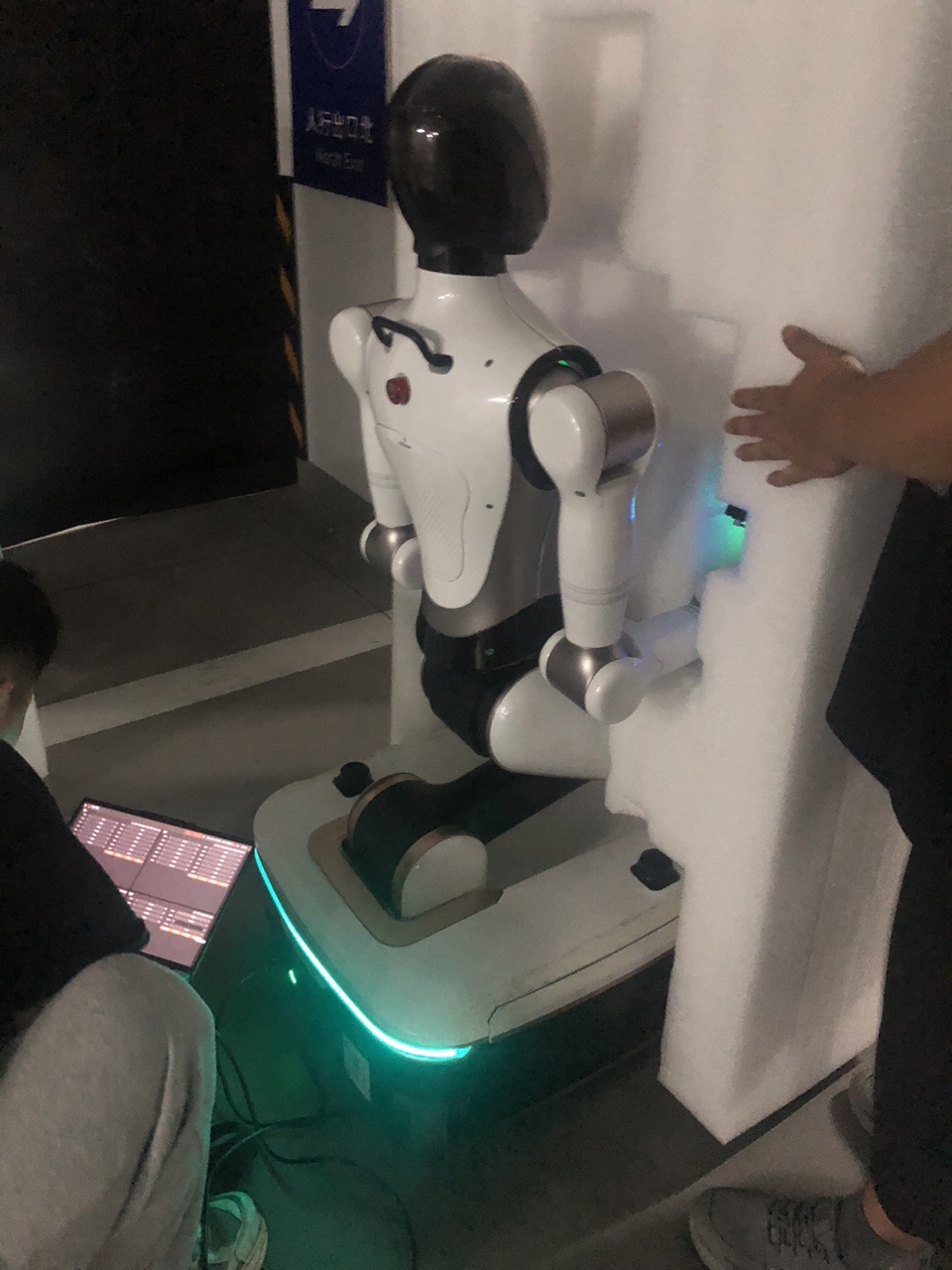
The packing angles of the 7 joints of the S2's left and right arms are as follows (in the current version, the packing buttons automatically move the arms to the angles below; no manual setting of packing angles is required):
| Joint 1 | Joint 2 | Joint 3 | Joint 4 | Joint 5 | Joint 6 | Joint 7 | |
|---|---|---|---|---|---|---|---|
| Left arm | 0 | 0 | 0 | -90 | 0 | 0 | 90 |
| Right arm | 0 | 0 | 0 | -90 | 0 | 0 | -90 |
One-Click Initial Pose
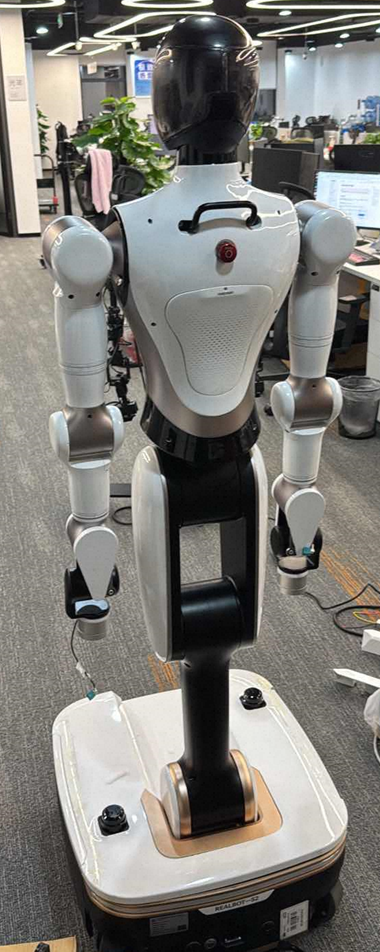
Press and hold the [One-Click Initial Pose] button to automatically return all joints of the head, waist, and arms of the robot to the zero position.
Joint Angle Control
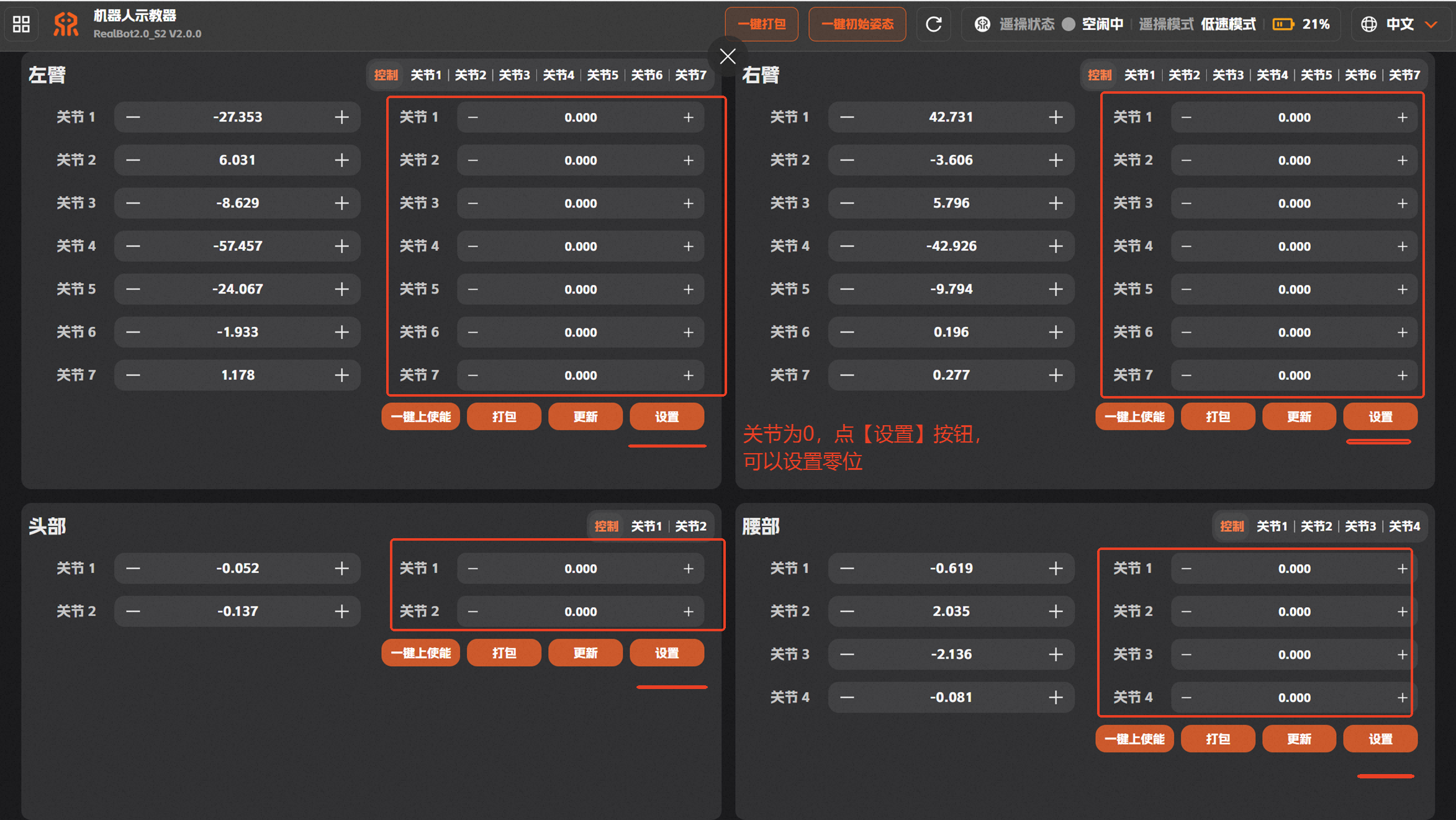
Adjust joint angles: To adjust the robot's joint pose, set the target joint in the second column of the joint teaching area of the left arm, right arm, head, or waist to the target angle, then press and hold the [Set] button to adjust the corresponding joint. (Note: for the left and right arms, joints are numbered 1 to 7 from the shoulder to the wrist.)
Return to zero position: In the head, waist, and arm areas, when all joint values in the second column are 0, press the [Set] button to return the corresponding part to the zero position.
Joint Enabling
One-click enable: When the head, waist, or arms have lost enablement, use the [One-Click Enable] button to enable the joints in the corresponding area in batch.
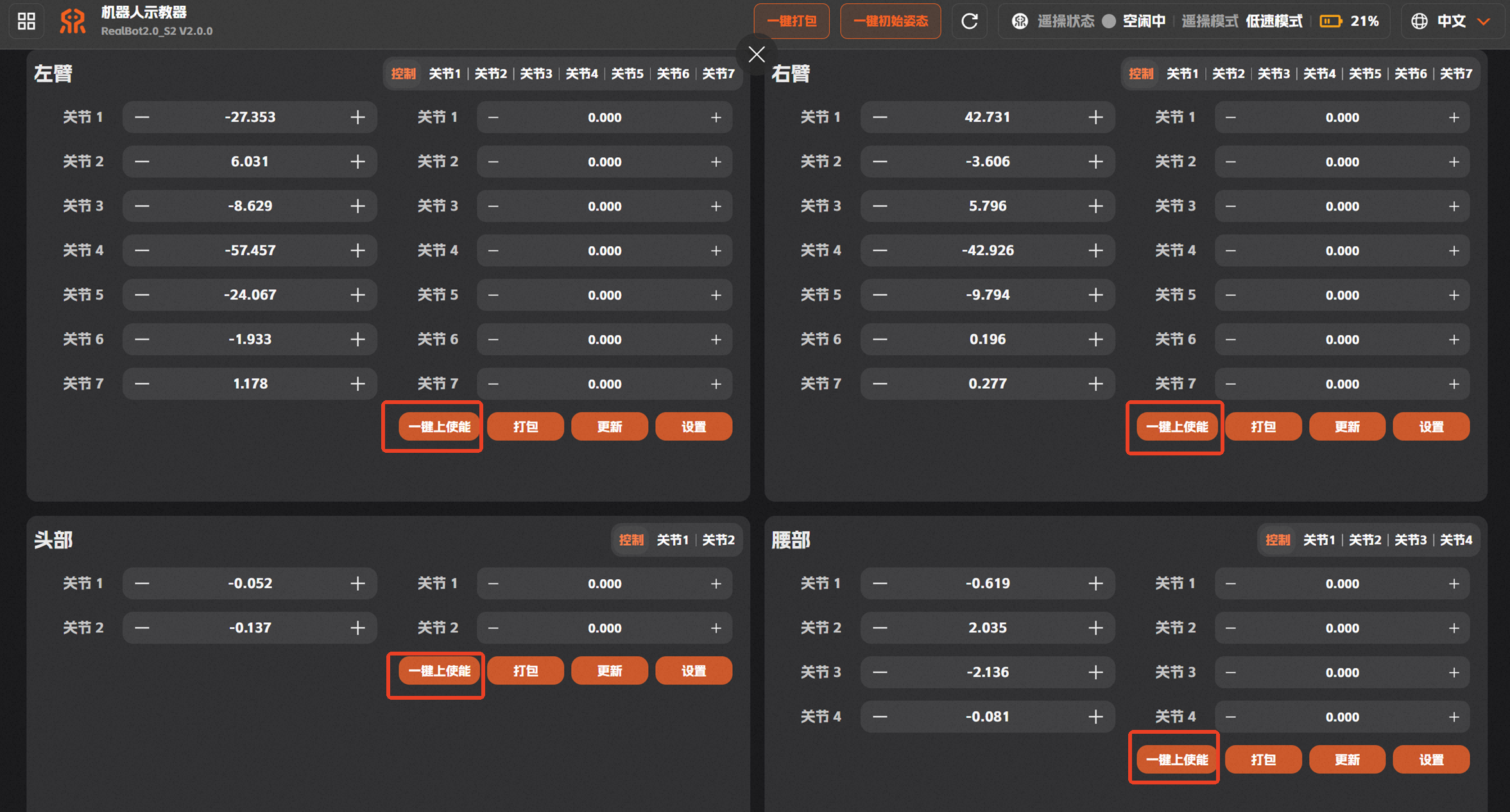
Single-joint enable/disable: When the head, waist, or arms have lost enablement or need to be disabled, use the [Enable] and [Disable] buttons to enable or disable the corresponding joints.
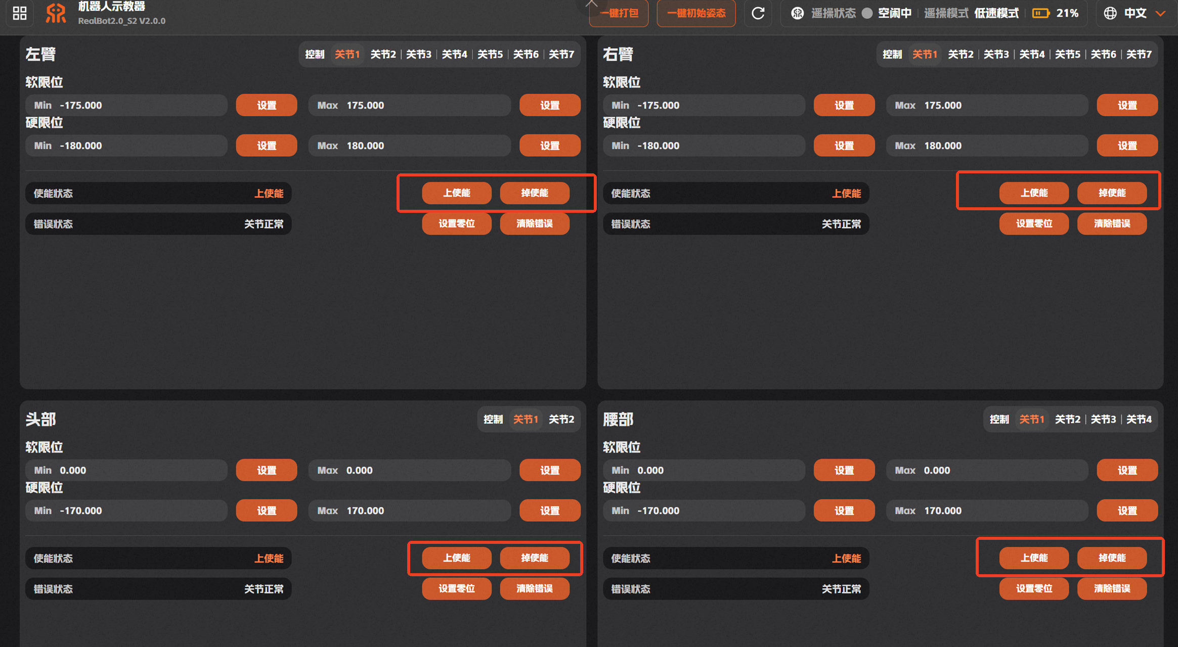
Joint Limits and Error Clearing
Notes on joint limits and the zero position for each joint tab on the "Joint Teaching" page:
The soft and hard joint limits have been defined with maximum and minimum values before delivery. In actual use:
Do not modify the software or hardware limits unless there is a special need.
If there is a special need, you may narrow the limit range, i.e., increase the minimum limit and decrease the maximum limit. The adjusted values must not exceed the original limit range. After modifying the maximum and minimum limits, you must [Disable] and then re-[Enable] the corresponding joint for the changes to take effect.
Set the zero position: The robot's zero position has been set before delivery. If the robot's zero position is accurate, users are not advised to reset the zero position of specific joints.
Clear errors: If a joint reports an error during use, click the [Clear Error] button of the corresponding joint to clear it.