

Quick Start:
Safety Guide General Safety Rules
Control Authority
Sole Sender: Before starting, confirm that no teach pendant, remote control, teleoperation program, or other client process is simultaneously issuing commands. Only one control sender is permitted at any time during operation; if exclusive control cannot be verified, do not proceed.
State Read‑back: A successful service return indicates only that the request has been received. It must never be used as a substitute for real‑time state read‑back and on‑site physical observation.
Mode Management
State Recording: Read and record the
system.alohaoperating state from/robot_slave/statesand the current display on the teach pendant. It is strictly forbidden to blindly switch operating states just to make an example “work”.Work Permit System: When a mode switch is indeed required, strictly follow the on‑site work permit procedure. After switching, re‑verify the system error flags, enable state, and current physical position.
Site Clearance and Supervision
Motion Envelope: Delineate the complete physical motion envelope of the manipulator arms, head/waist, and chassis. Remove all obstacles within the envelope and confirm that the equipment is not in charging or maintenance status.
Two‑person Supervision: Assign a dedicated on‑site supervisor. The operator and supervisor must agree in advance on the operation objective, abort conditions, and expected motion direction.
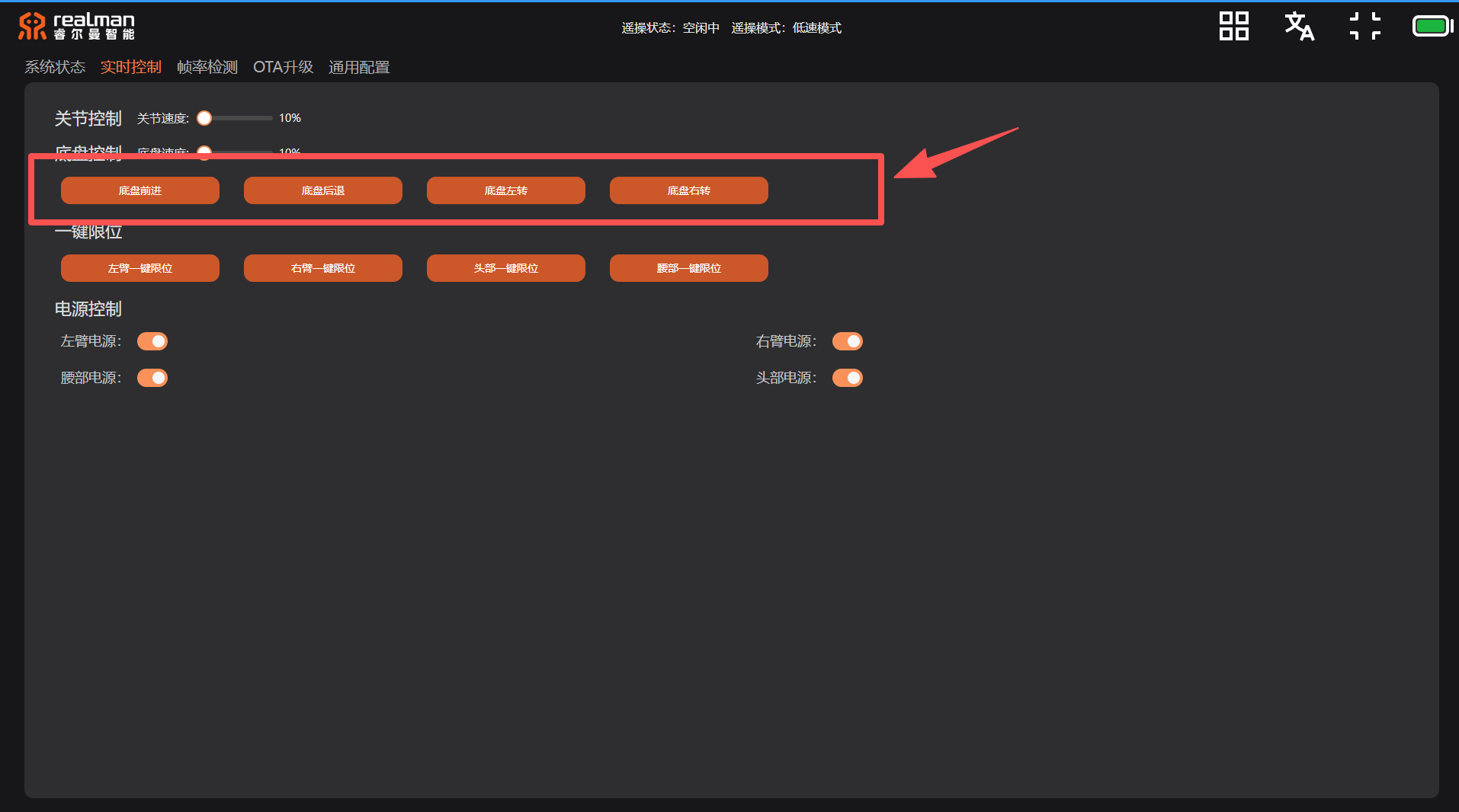
Chassis Boundary: When performing chassis motion operations, additionally reserve sufficient physical braking distance and a safety margin against falls.
Emergency Stop Mechanism
Reachability Requirement: The physical emergency‑stop device must be within immediate reach at all times and confirmed functional through the on‑site safety procedure.
Software Limitations: Software‑level termination interfaces (Topic / REST) serve only as supplementary measures and can never replace the physical emergency‑stop device.
Immediate Interruption: Immediately abort the current operation if any abnormal motion direction, over‑limit tendency, error flag trigger, or communication interruption occurs.
Limit Mechanisms
Boundary Query: Before motion, call the read‑only interface to obtain the current joint angles and the hardware limits of the actuators (the baseline head actuator range is ±22° per axis; the actual values returned by the real‑time device shall prevail).
Test Restrictions: Example scripts limit the head relative target to no more than 3° per axis, with the speed level fixed at
1, and simultaneously verify the absolute target value. It is strictly forbidden to modify soft/hard limit parameters using examples from this manual.
Safety Stop Mechanism
- Channel Confirmation: Before starting motion, clearly identify the termination method for that control channel:
- Upper body REST: Call
move/setArmStop; - Head/waist ROS service: Send a stop command through the controlled link;
- Chassis control: Stop continuous velocity publication and send a zero‑velocity command (the authorised solution may call
/StopMotor).
- Upper body REST: Call
- Prohibition of Disable:
/DisEnableMotorwill de‑energise the components that maintain upper‑body posture, causing them to droop. It is strictly forbidden to use this as a routine wrap‑up action.
- Channel Confirmation: Before starting motion, clearly identify the termination method for that control channel:
Recovery Mechanism
- Pose Preservation: Before sending a command, save the original joint values or chassis pose.
- Return and Verification: After the action is complete, return to the original state and re‑read the position and error flags. The head return tolerance is set to 0.05° per axis; if this tolerance is exceeded or if
sys_err/joint_erris non‑zero, the operation is deemed abnormal. Do not continuously attempt new actions to mask the issue.
Hardware Connection and Control Addresses
The development computer must be connected via Ethernet cable to the robot chassis LAN port, configured to the same subnet
192.168.127.0/24. Then complete the ping connectivity check, version query, and SSH read‑only inspection as described in Connecting to the Robot.Development Guidelines: The addresses in the table below belong to the current delivery version. Hard‑coding them in customer engineering code is strictly prohibited.
Control Object IP and Port Usage Boundary Orin control entry 192.168.127.10; REST 9091, ROS2Official primary path for customers; REST supports small‑motion control for both arms and head/waist via the controlled route. Left actuator controller 192.168.127.18:8080Supports TCP connectivity and read‑only query get_arm_software_info; motion messages must follow the 4th‑generation controller JSON protocol.Right actuator controller 192.168.127.19:8080Supports TCP connectivity and read‑only query get_arm_software_info; motion messages must follow the 4th‑generation controller JSON protocol.S100 head/waist controller 192.168.127.11:8080Supports TCP port connectivity; under software V1.2.9‑dr / hardware 1.2, supports actuator limit reading, 1° head reciprocation and 0.2° waist reciprocation, and stop acknowledgement. Direct S100 connection is not yet open. TIP
- Re‑read the current state before any motion.
- If an error occurs on any part, stop immediately and follow the fault diagnosis procedure.
Teach Pendant Operation Entry Identification
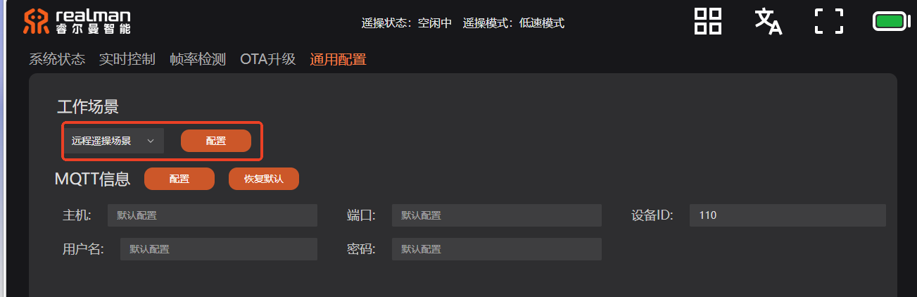
The following screenshots are only provided to identify relevant operation entries on the teach pendant. No motion control command shall be issued before all eight general safety rules above are fully satisfied.
Safety and Operations
- Read‑only: Does not cause robot motion, alter operating states, or write business data.
- Controllable Risk: May cause robot motion or change recoverable states; execution requires on‑site safety supervisor and physical emergency‑stop button kept within immediate reach, and must follow the low‑speed, small‑amplitude operation principle. After completion, perform state recovery verification.
- High Risk: Involves service stoppage, configuration modification, upgrade, system tuning, or disk cleanup, etc.; requires explicit authorisation, impact scope confirmation, and a complete recovery plan before execution.
TIP
All control operations must strictly follow the safety operation workflow:
Read state → Small‑step command → State feedback evaluation → Stop and returnThe robot supports security mechanisms including SSH host fingerprint verification and Bearer Token authentication (HTTP Bridge).