Ontology Parameters:
RML63 Series Parameters and D-H Model Basic Parameters
| Parameter Name | Parameter Value | |
|---|---|---|
| Basic Parameters | Degrees of Freedom | 6 |
| Configuration | Humanoid Configuration | |
| Joint Brake Type | Joints 1 to 3: Hard Brake Joints 4 to 6: Soft Brake | |
| Working Radius/mm | Standard Version: 900 Six-Axis Force L Version: 917 Six-Axis Force K Version: 928.5 | |
| Payload/kg | 3 | |
| Self-weight/kg | Standard Version: 10 Six-Axis Force Version: 10.1 | |
| Repeatability/mm | ±0.05 | |
| TCP Line Speed/m/s | ≤2.8 | |
| Typical Power/W | ≤150 | |
| Peak Power/W | ≤900 | |
| Installation Angle | Any Angle | |
| Base Dimensions/mm | φ107 | |
| Material | Aluminum Alloy/ABS | |
| Environmental Adaptability | Operating Temperature/℃ | 0-45 |
| Operating Humidity | 25~85% Non-condensing | |
| Motion Angle Range/° | J1 | -178~+178 |
| J2 | -178~+178 | |
| J3 | -178~+145 | |
| J4 | -178~+178 | |
| J5 | -178~+178 | |
| J6 | -360~+360 | |
| Maximum Angular Velocity/°/s | J1 | 180 |
| J2 | 180 | |
| J3 | 225 | |
| J4 | 225 | |
| J5 | 225 | |
| J6 | 225 | |
| Force Control Specifications (Supported only by 6-DoF sensors) | Six-Axis Force Range | 200N/7N·m |
| Six-Axis Force Accuracy | ±0.5%FS | |
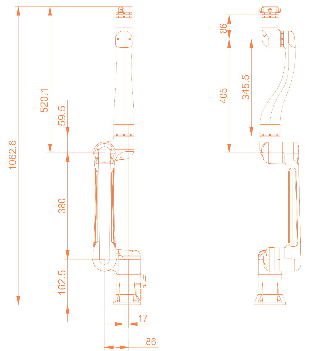
Ontology Parameters
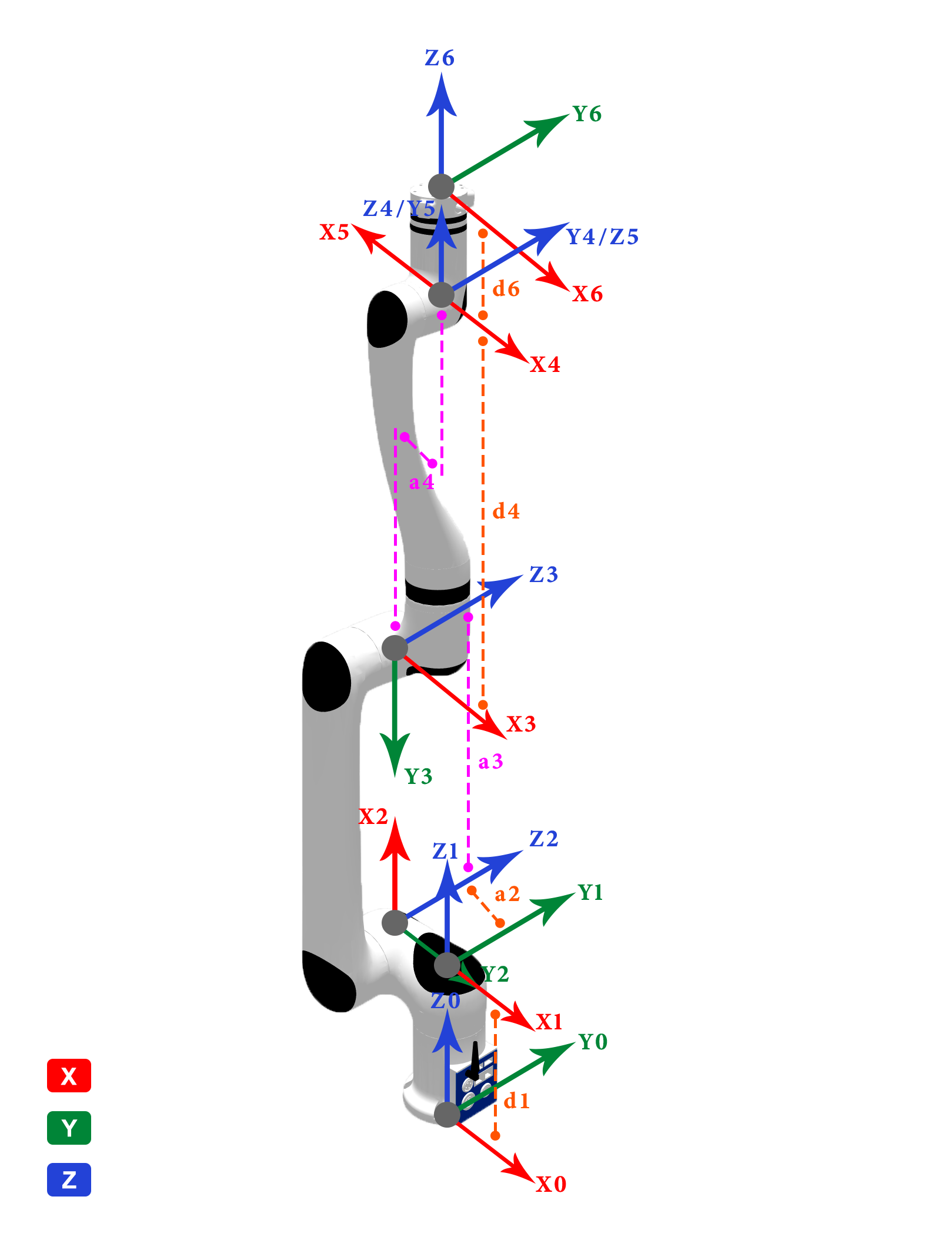
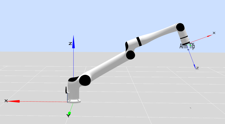
MDH model frame:
MDH parameters of RML63 (modified D-H parameters):
| Joint No.(i) | ||||
|---|---|---|---|---|
| 1 | 0 | 0 | 0 | |
| 2 | -86 | -90 | 0 | -90 |
| 3 | 380 | 0 | 0 | 90 |
| 4 | 69 | 90 | 405 | 0 |
| 5 | 0 | -90 | 0 | 180 |
| 6 | 0 | -90 | 180 |
- RML63II :
mm - RML63III :
mm - RML63-6FB-V :
mm - RML63-B-V :
mm - RML63-B :
mm - RML63-6FB :
mm - RML63-6F :
mm
Note:
- offset refers to the offset of the joint zero position from the model zero position, that is,
model angle = joint angle + offset. - The RML63 series robotic arm comes in two versions, Type II and Type III, with the main difference being the length of joint 1.
Kinetic parameters of RML63 robot link
RML63II:
| joint_id(i) | 1 | 2 | 3 | 4 | 5 | 6 | - | - |
|---|---|---|---|---|---|---|---|---|
| 1.837 | 2.006 | 1.961 | 1.201 | 1.026 | 0.107 | 0.248 | 0.189 | |
| -68.442 | 166.7 | 33.399 | 0 | -0.031 | -0.506 | -0.426 | -0.352 | |
| -23.913 | -0.002 | -29.498 | -35.177 | 30.146 | 0.255 | 0.237 | -0.067 | |
| -6.938 | -92.59 | -17.697 | -184.4 | -12.341 | -10.801 | -27.223 | -18.302 | |
| 3462.129 | 18664.833 | 6432.819 | 53007.563 | 2732.466 | 50.918 | 308.844 | 133.613 | |
| -3765.305 | -0.587 | 3869.875 | -0.04 | -2.123 | -3.136 | -3.781 | 0.522 | |
| -46.206 | 30804.14 | 17.607 | 0.087 | 0.374 | -0.699 | -1.468 | 1.623 | |
| 12643.164 | 103568.483 | 7094.216 | 50754.293 | 829.793 | 47.42 | 304.616 | 130.260 | |
| -50.044 | -0.287 | -17.611 | -5089.754 | -2.288 | 0.388 | 0.888 | 0.531 | |
| 13576.758 | 86722.559 | 9257.063 | 2874.631 | 2384.323 | 60.35 | 122.62 | 89.503 | |
| Remarks | B | 6F | 6FB |
RML63III:
| joint_id(i) | 1 | 2 | 3 | 4 | 5 | 6 | - | - |
|---|---|---|---|---|---|---|---|---|
| 1.598 | 2.990 | 1.357 | 1.864 | 1.023 | 0.107 | 0.248 | 0.189 | |
| -12.900 | 109.800 | 14.100 | -0.100 | 0.100 | -0.506 | -0.426 | -0.352 | |
| 0.100 | 0.100 | -5.600 | -23.000 | 32.600 | 0.255 | 0.237 | -0.067 | |
| -29.800 | -64.200 | -29.400 | -236.200 | -15.200 | -10.801 | -27.223 | -18.302 | |
| 3150.724 | 16728.188 | 3116.708 | 128352.380 | 3299.439 | 50.918 | 308.844 | 133.613 | |
| -18.047 | -17.784 | 508.850 | -4.255 | -1.019 | -3.136 | -3.781 | 0.522 | |
| -13.564 | 26077.237 | -1.031 | -52.273 | 0.0317 | -0.699 | -1.468 | 1.623 | |
| 4867.960 | 102753.087 | 4083.881 | 125960.777 | 1008.186 | 47.42 | 304.616 | 130.260 | |
| 6.612 | 12.608 | 3.755 | -4630.083 | 0.336 | 0.388 | 0.888 | 0.531 | |
| 2833.691 | 88450.085 | 2455.232 | 3681.884 | 2745.436 | 60.35 | 122.62 | 89.503 | |
| Remarks | B | 6F | 6FB |
Description:
is the mass of the link, is the x-coordinate of the center of mass of link, is the y-coordinate of the center of mass of link, is the z-coordinate of the center of mass of link, , , , , , is the principal moment of inertia described in the link frame, - B: standard version, 6FB: Six-Axis Force L Version, 6F: six-axis force K version
Remarks:
- Source of data: CAD design values.
- If the inertial parameters in the center of mass frame are required, they can be calculated based on the parallel axis theorem, as stated below.
Assuming there is an output frame
Where,
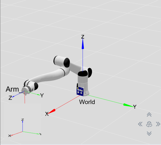
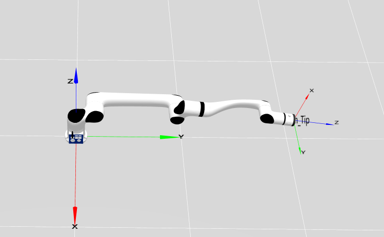
Distribution and dimensions of joints
The RML63-B humanoid robotic arm has six rotating joints, each of which represents one degree of freedom. As shown in the figure below, robot joints include the shoulders (joint 1 and joint 2), elbow (joint 3), and wrists (joint 4, joint 5, and joint 6).

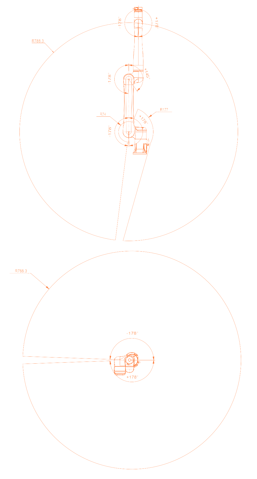
Workspace
The workspace of RML63-B is a sphere with a working radius of 900 mm, in addition to the cylindrical space directly above and below the base. When determining the installation position of the robot, due considerations must be given to the cylindrical space directly above and below the robot, to avoid moving tools to this cylindrical space as much as possible. Furthermore, in actual applications, the motion ranges of all joints are as follows: joint 1: ±178°; joint 2: ±178°; joint 3: -178° to +145°; joint 4: ±178°; joint 5: ±178°; joint 6: ±360°.
Motion singularities - RML63III
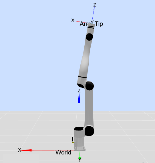
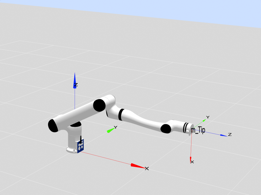
Singular Type 1: Shoulder singularity
When the intersection point of the axes of Joint 5 and Joint 6 lies on the plane that passes through the axis of Joint 1 and is parallel to the axis of Joint 2, a shoulder singularity occurs.
The shoulder singularity is shown in the figure below. The blue plane in the figure is the plane that passes through the axis of Joint 1 and is parallel to the axis of Joint 2.
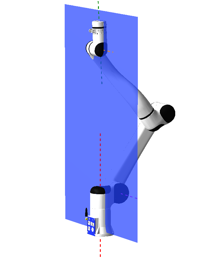
Example point 1: [0,-34.85,72.738,0,-35,0], as shown in the figure below:
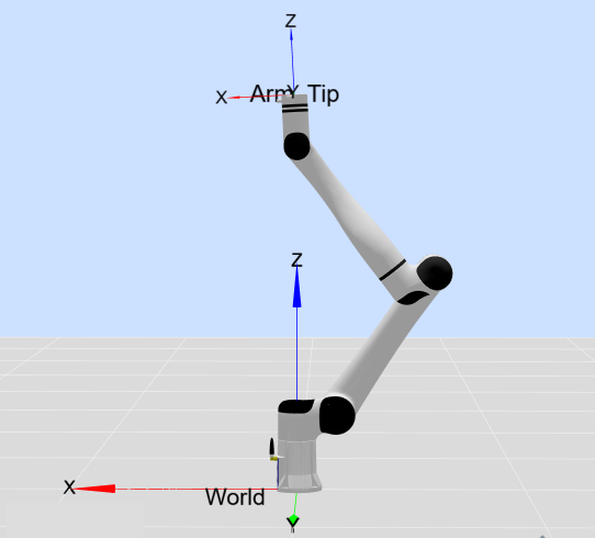
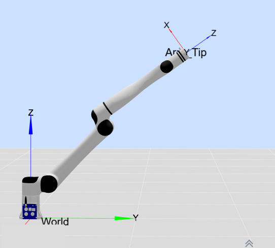
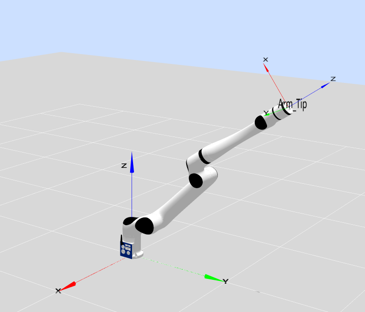
Singular Type 2: Elbow singularity
When the intersection point of the axes of Joint 5 and Joint 6 lies on the plane formed by the axes of Joint 2 and Joint 3, an elbow singularity occurs.
Example point 1: [0,-60,-9.684,0,-90,0], as shown in the figure below:
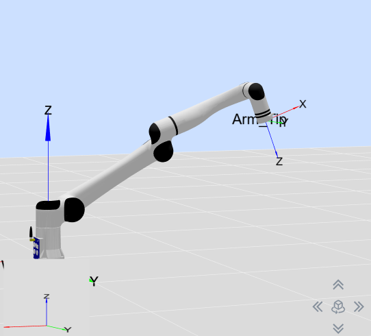
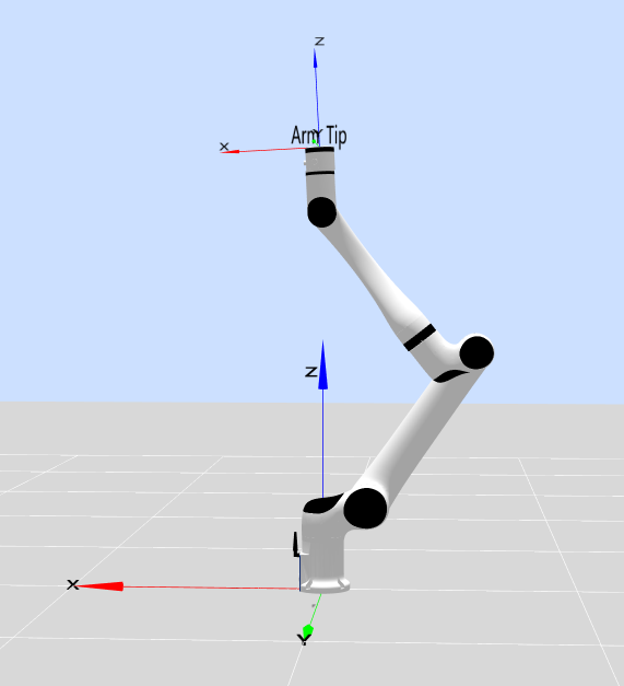
Singular Type 3: Wrist singularity
When the axes of Joint 4 and Joint 6 are parallel, q5=0, i.e., the point format is [x,x,x,x,0,x], a wrist singularity occurs.
Example point 1: [0,60,30,0,0,0], as shown in the figure below:
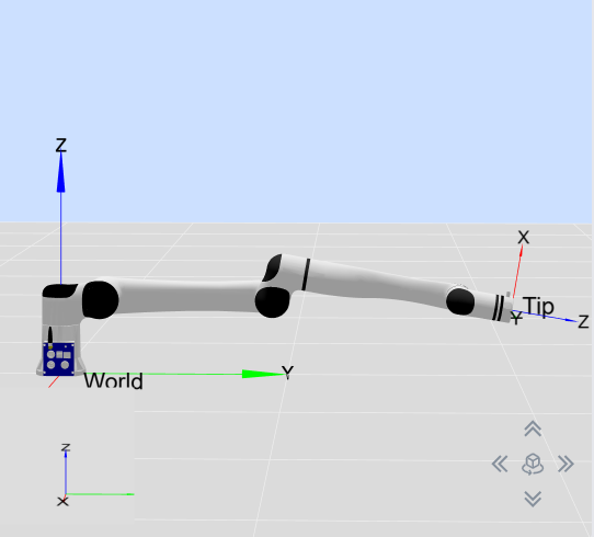
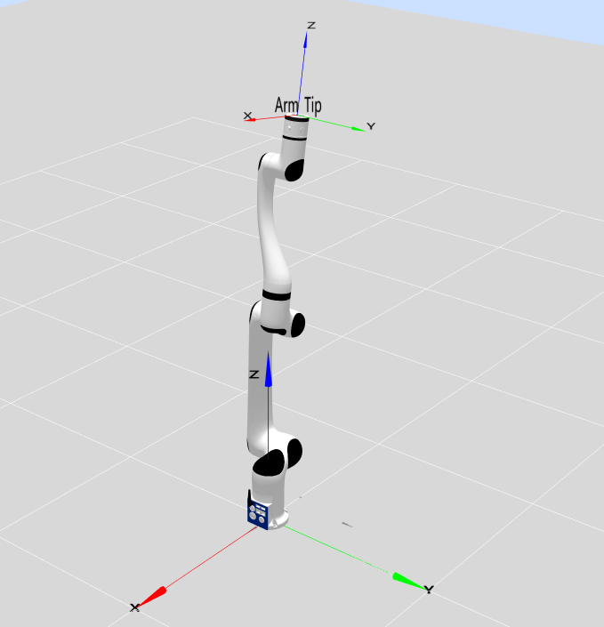
Singular Type 4: Boundary singularity
When the robot end-effector reaches the farthest point, q3=-9.683 and q5=0, i.e., the point format is [x,x,-9.683,x,0,x], a boundary singularity occurs.
Example point 1: [0,0,-9.683,0,0,0], as shown in the figure below:
Example point 2: [-90,-45,-9.683,0,0,0], as shown in the figure below:
Example point 3: [-90,-90,-9.683,0,0,0], as shown in the figure below:
Motion Singularities - RML63II
Singularity Type 1: Shoulder Singularity
When the intersection point of the axes of Joint 5 and Joint 6 lies on the plane that passes through the axis of Joint 1 and is parallel to the axis of Joint 2, a shoulder singularity occurs.
The shoulder singularity is shown in the figure below. The blue plane in the figure refers to the plane that passes through the axis of Joint 1 and is parallel to the axis of Joint 2:
Example point 1: [0,-34.85,72.738,0,-35,0], as shown in the figure below:
Singularity Type 2: Elbow Singularity
When the intersection point of the axes of Joint 5 and Joint 6 lies on the plane formed by the axes of Joint 2 and Joint 3, an elbow singularity occurs.
Example point 1: [0,-60,-9.684,0,-90,0], as shown in the figure below:
Singularity Type 3: Wrist Singularity
When the axes of Joint 4 and Joint 6 are parallel, q5=0, i.e., the point format is [x,x,x,x,0,x], a wrist singularity occurs.
Example point 1: [0,60,30,0,0,0], as shown in the figure below:
Singularity Type 4: Boundary Singularity
When the robot end-effector reaches the farthest point, q3=-9.683 and q5=0, i.e., the point format is [x,x,-9.683,x,0,x], a boundary singularity occurs.
Example point 1: [0,0,-9.683,0,0,0], as shown in the figure below:
Example point 2: [-90,-45,-9.683,0,0,0], as shown in the figure below:
Example point 3: [-90,-90,-9.683,0,0,0], as shown in the figure below:
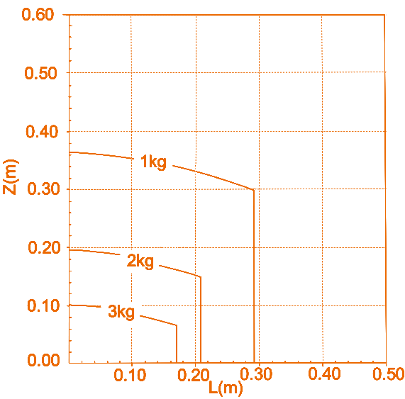
Load curves
Represent the end load curves of RML63-B and RML63-6F and RML63-6FB. Where, L refers to the radial distance of the center of mass of end load against the plane of end flange, and Z refers to the normal distance of the center of mass of end load against the plane of end flange.