Ontology Parameters:
RX75 Series Parameters and D-H Model Basic Parameters
| Parameter Name | Parameter Value | |
|---|---|---|
| Basic Parameters | Degrees of Freedom | 7 |
| Configuration | Humanoid Configuration | |
| Joint Brake Type | Joints 1~4: Hard Brake Joints 5~7: Soft Brake | |
| Working Radius/mm | Six-Axis Force Version: 709.2 Six-Axis Force + Vision Version: 732 | |
| Effective Rated Payload/kg | 5 | |
| Self-weight/kg | Six-Axis Force Version: 8.2 Six-Axis Force + Vision Version: 8.4 | |
| Repeatability/mm | ±0.2 | |
| TCP Line Speed/m/s | ≤2.2 | |
| Typical Power/W | ≤200 | |
| Instant Peak Power/W | ≤1000 | |
| Installation Angle | Side Mount: Ry=-90 ° | |
| Base Dimensions/mm | φ102 | |
| Material | Aluminum Alloy/ABS | |
| End Camera | D405 (Standard on Vision Version) | |
| Environmental Adaptability | Operating Temperature/℃ | 0-45 |
| Operating Humidity | 25~85% Non-condensing | |
| Motion Angle Range/° | J1 | -173~+173 |
| J2 | -35~+178 | |
| J3 | -173~+173 | |
| J4 | -130~+15 | |
| J5 | -173~+173 | |
| J6 | -55~+55 | |
| J7 | Left Arm: -109~+35 Right Arm: -35~+109 | |
| Maximum Angular Velocity/°/s | J1 | 180 |
| J2 | 180 | |
| J3 | 225 | |
| J4 | 225 | |
| J5 | 225 | |
| J6 | 225 | |
| J7 | 225 | |
| Force Control Specifications (Supported only by 6-DoF sensors) | Six-Axis Force Range | 200N/7N·m |
| Six-Axis Force Accuracy | ±0.5%FS | |
Ontology Parameters
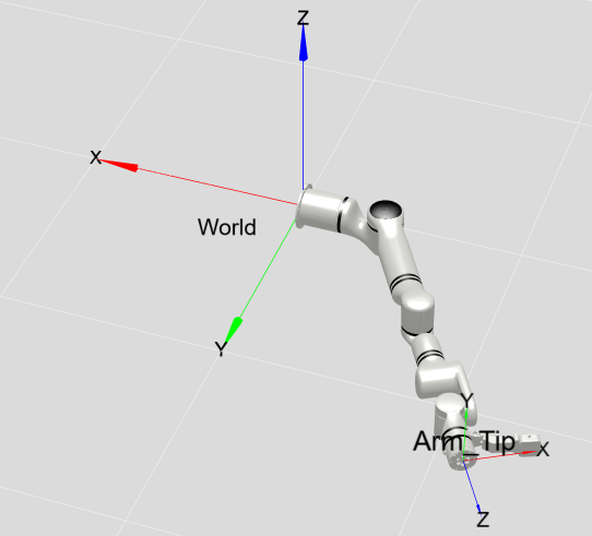
MDH Model Frame:
MDH Parameters of Left-Arm RXL75 Series (Modified D-H Parameters):
Installation Info: Ry=-90°
| joint_id(i) | Remarks | ||||
|---|---|---|---|---|---|
| 1 | 0 | 0 | 191.5 | 0 | |
| 2 | 0 | -90 | 0 | -90 | |
| 3 | 0 | 90 | 322 | 90 | |
| 4 | 0 | 90 | 0 | 0 | |
| 5 | 0 | -90 | 275.5 | 0 | |
| 6 | 0 | 90 | 0 | 90 | |
| 7 | 15.5 | 90 | 0 | 90 | |
| 8 | 0 | 90 | 96.2 | 0 | (6FB) Integrated Six-Axis Force |
| 119 | (6FB-V) Integrated Six-Axis Force + Vision |
Note: offset refers to the offset of the mechanical zero position from the model zero position, that is, model angle = joint angle + offset.
MDH Parameters of Right-Arm RXR75 Series (Modified D-H Parameters):
Installation Info: Ry=-90°
| joint_id(i) | Remarks | ||||
|---|---|---|---|---|---|
| 1 | 0 | 0 | 191.5 | 0 | |
| 2 | 0 | -90 | 0 | -90 | |
| 3 | 0 | 90 | 322 | -90 | |
| 4 | 0 | 90 | 0 | 0 | |
| 5 | 0 | -90 | 275.5 | 0 | |
| 6 | 0 | 90 | 0 | 90 | |
| 7 | 15.5 | 90 | 0 | -90 | |
| 8 | 0 | -90 | 96.2 | 0 | (6FB) Integrated Six-Axis Force |
| 119 | (6FB-V) Integrated Six-Axis Force + Vision |
Note: offset refers to the offset of the mechanical zero position from the model zero position, that is, model angle = joint angle + offset.
Kinetic Parameters of RX75 Series Link
Left Arm:
| Joint No. | ||||||||||
|---|---|---|---|---|---|---|---|---|---|---|
| 1 | 3136.43 | 41.478 | -1.145 | 2483.576 | 78.947 | 1970.778 | -0.488 | -13.727 | -10.765 | 1.559 |
| 2 | 37530.89 | 22.717 | 2.041 | 1068.573 | -47.546 | 37444.566 | -0.112 | -148.134 | 4.111 | 1.394 |
| 3 | 2171.46 | -0.149 | -4.264 | 1609.222 | -83.494 | 1253.185 | 0.032 | 15.649 | -11.225 | 1.117 |
| 4 | 6216.32 | 0.007 | -0.007 | 359.898 | 48.906 | 6174.838 | -0.001 | 85.449 | 4.844 | 0.673 |
| 5 | 9937.67 | -0.063 | 0.082 | 9288.177 | 899.812 | 1337.425 | -0.001 | -14.741 | -80.627 | 1.13 |
| 6 | 360.632 | -8.175 | -2.382 | 402.132 | -1.155 | 421.185 | 13.909 | -1.02 | 3.245 | 0.559 |
| 7 | 3254.6 | -841.422 | 0.811 | 1355.093 | -17.714 | 4268.534 | 20.024 | -71 | 4.396 | 0.483 |
Right Arm:
| Joint No. | ||||||||||
|---|---|---|---|---|---|---|---|---|---|---|
| 1 | 3144.289 | -0.096 | -2.729 | 2483.576 | 22.265 | 1953.83 | 0.018 | -13.67 | -10.1 | 1.559 |
| 2 | 37594.181 | 42.369 | -3.602 | 1049.311 | 56.439 | 37524.126 | -0.197 | -149.264 | -3.905 | 1.384 |
| 3 | 2170.993 | 6.949 | 2.336 | 1609.222 | 84.454 | 1253.793 | -0.154 | -15.652 | -11.241 | 1.117 |
| 4 | 6201.568 | -0.116 | -0.007 | 345.166 | -48.523 | 6170.874 | 0 | 86.537 | -4.411 | 0.665 |
| 5 | 9937.599 | -0.05 | -0.006 | 9283.329 | -899.736 | 1337.249 | 0 | 14.739 | -80.627 | 1.13 |
| 6 | 360.168 | -8.3 | 2.383 | 402.131 | 1.103 | 421.185 | 13.908 | -1.017 | -3.245 | 0.559 |
| 7 | 3254.587 | 841.524 | -0.805 | 1355.088 | 15.095 | 4268.521 | 20.008 | 71 | 4.302 | 0.483 |
Description:
: Mass of the link, unit: : X-coordinate of the center of mass of the link, unit: : Y-coordinate of the center of mass of the link, unit: : Z-coordinate of the center of mass of the link, unit: , , , , , : Principal moments of inertia described in the link coordinate system, unit:
Remarks:
- Data above are sourced from CAD design values.
- If inertial parameters in the center of mass coordinate system are required, the Parallel Axis Theorem can be used. The calculation method is described as follows.
Assuming an output coordinate system
Where:
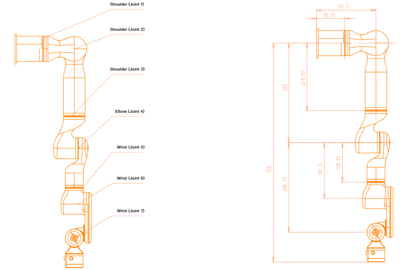
Joint Distribution and Dimension Description
The RX75 robot imitates the human arm and has 7 rotational joints, each representing one degree of freedom. As shown in the figures below, the robot joints include shoulder (joint 1), shoulder (joint 2), shoulder (joint 3), elbow (joint 4), wrist (joint 5), wrist (joint 6), and wrist (joint 7).
RXBL - Joint Distribution:
RXBR - Joint Distribution:
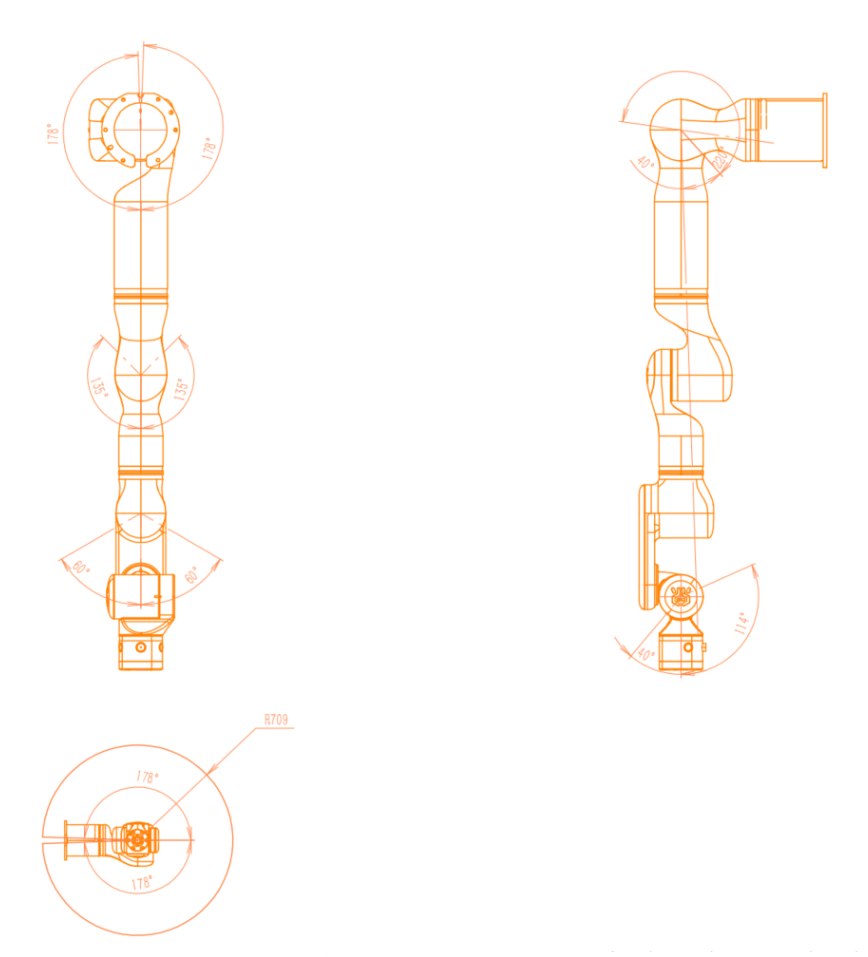
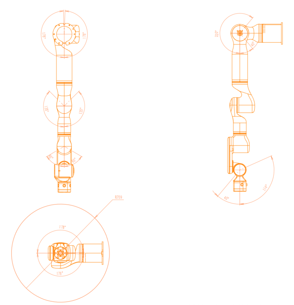
Workspace
Excluding the cylindrical space directly above and below the base, the workspace of RX75 is a sphere with a radius of 709 mm (732 mm for the vision version). When selecting the robot installation position, be sure to consider the cylindrical space directly above and below the robot and avoid moving the tool into this area as much as possible.
In actual applications: Joint 1 range: ±173 ° Joint 2 range: -35 ~ +178 ° Joint 3 range: ±173 ° Joint 4 range: -130 ~ +15 ° Joint 5 range: ±173 ° Joint 6 range: ±55 ° Joint 7 left arm: -109 ~ +35 ° Joint 7 right arm: -35 ~ +109 °
RXBL - Workspace:
RXBR - Workspace:
Motion Singularities
Left Arm: RXL75
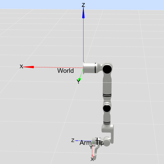
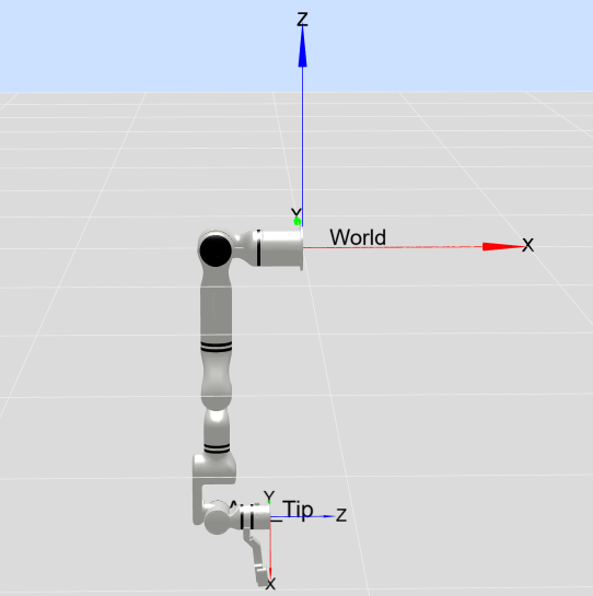
Singularity Type 1
When q4=0, i.e., the point format is [x,x,x,0,x,x,x].
Example point 1: [-90,30,-90,0,90,0,0], as shown in the figure below:
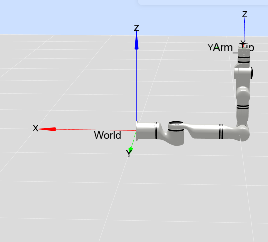
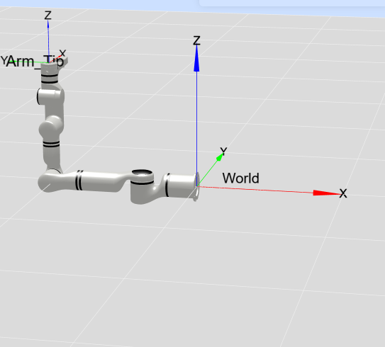
Example point 2: [0,0,90,0,-90,0,-90], as shown in the figure below:
Singularity Type 2
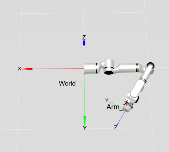
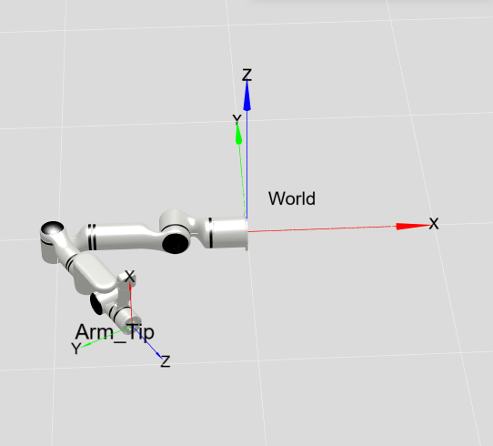
When q2=90 and q3=0 (or q3=180), i.e., the point format is [x,90,0 or 180,x,x,x,x].
Example point 1: [-90,90,0,-90,0,0,0], as shown in the figure below:
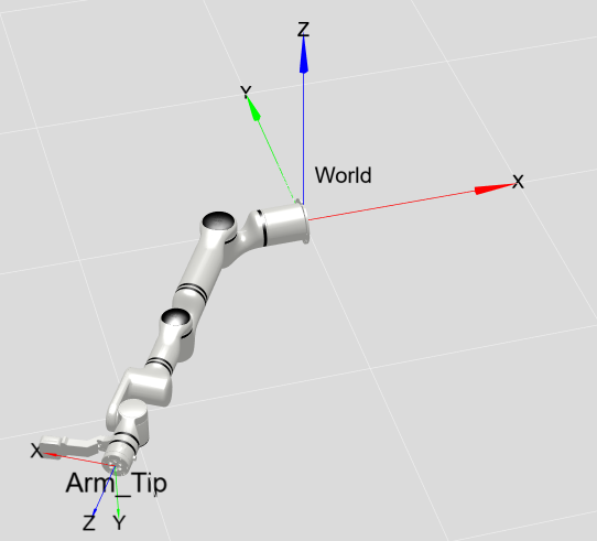
Example point 2: [0,90,0,-120,0,0,0], as shown in the figure below:
Right Arm: RXR75
Singularity Type 1
When q4=0, i.e., the point format is [x,x,x,0,x,x,x].
Example point 1: [90,30,-90,0,90,0,0], as shown in the figure below:
Example point 2: [0,0,90,0,-90,0,90], as shown in the figure below:
Singularity Type 2
When q2=90 and q3=0 (or q3=180), i.e., the point format is [x,90,0 or 180,x,x,x,x].
Example point 1: [90,90,0,-90,0,0,0], as shown in the figure below:
Example point 2: [0,90,0,-120,0,0,0], as shown in the figure below:
Load Curves
The following figures show the end load curves of RX75-6FB and RX75-6FB-V manipulators. Where L is the radial distance from the center of mass of the end load to the end flange plane, and Z is the normal distance from the center of mass of the end load to the end flange plane.