Start guide:
Teaching Pendant Operation Guide Users can program the RM65 series robots through the Graphical Programming interface to achieve complex robot movements.
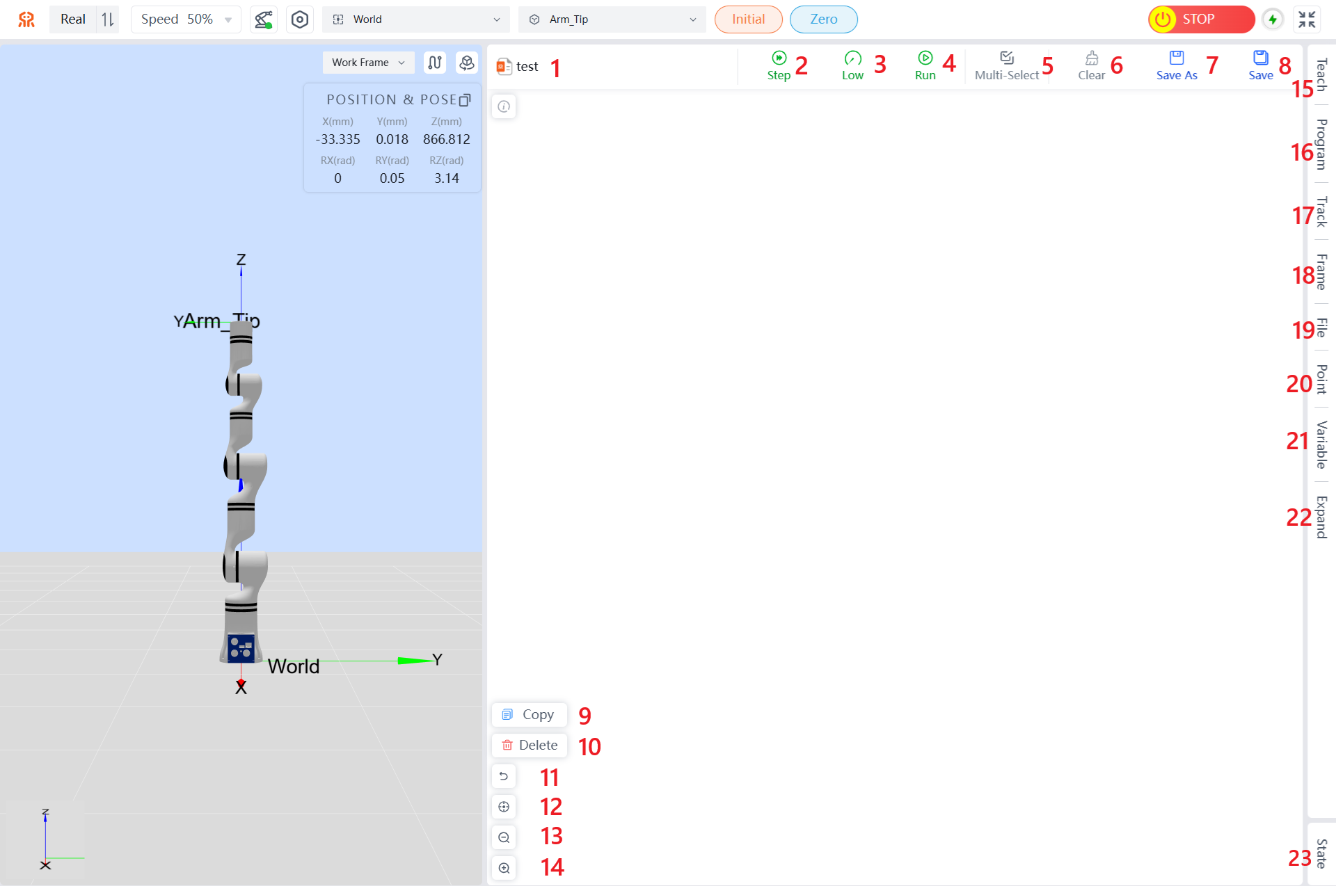
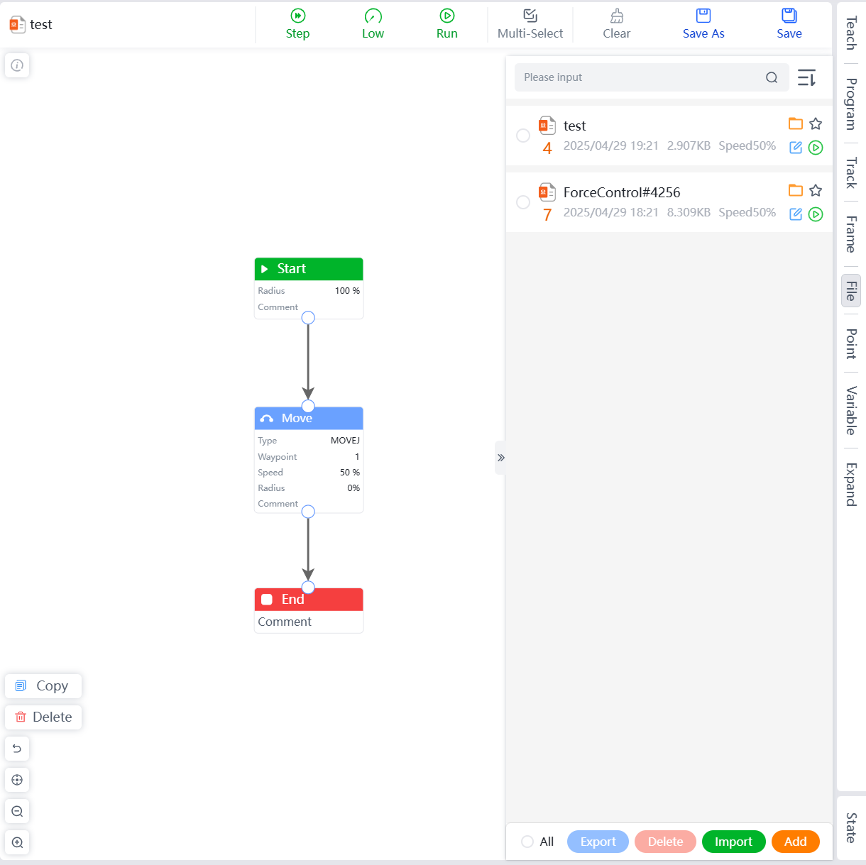
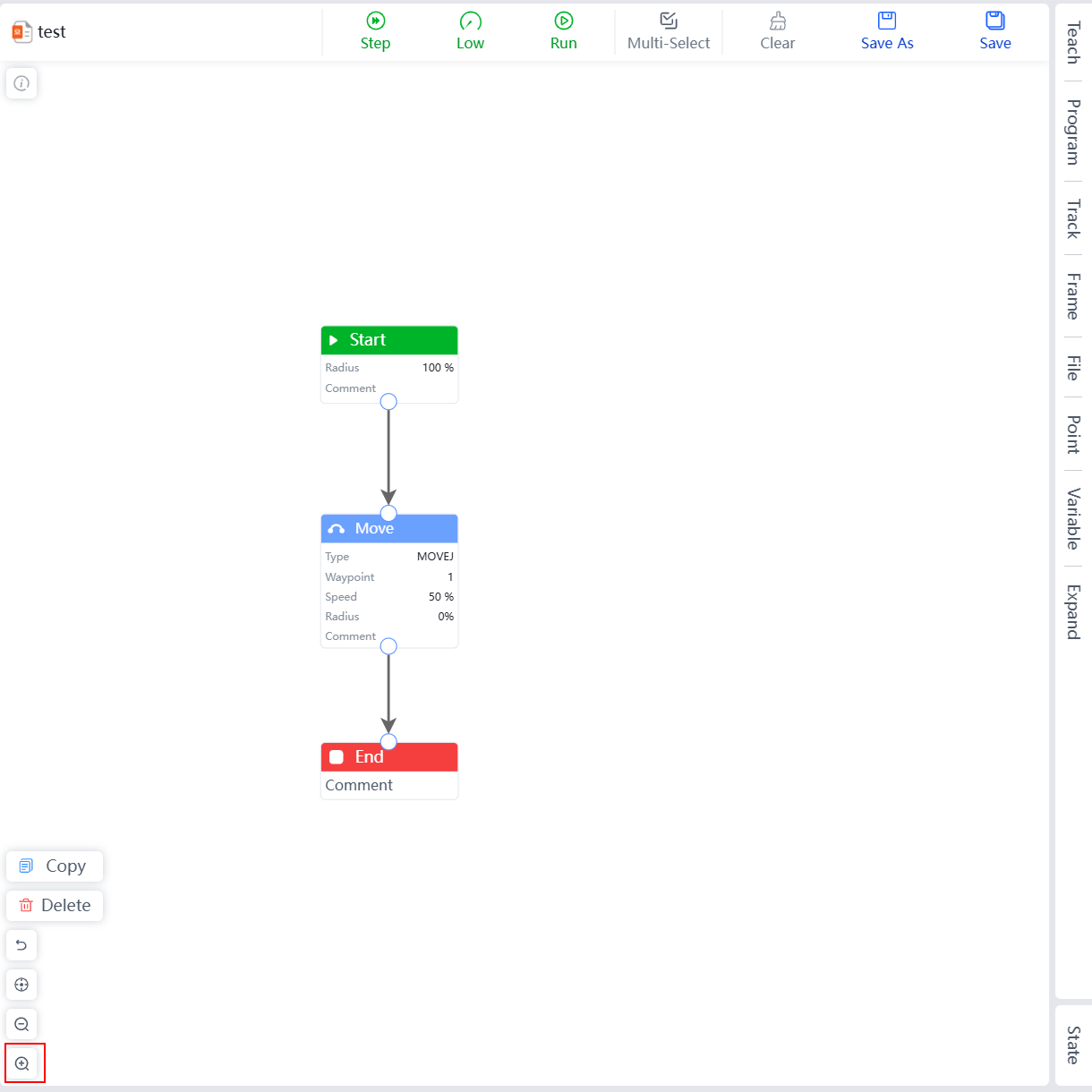
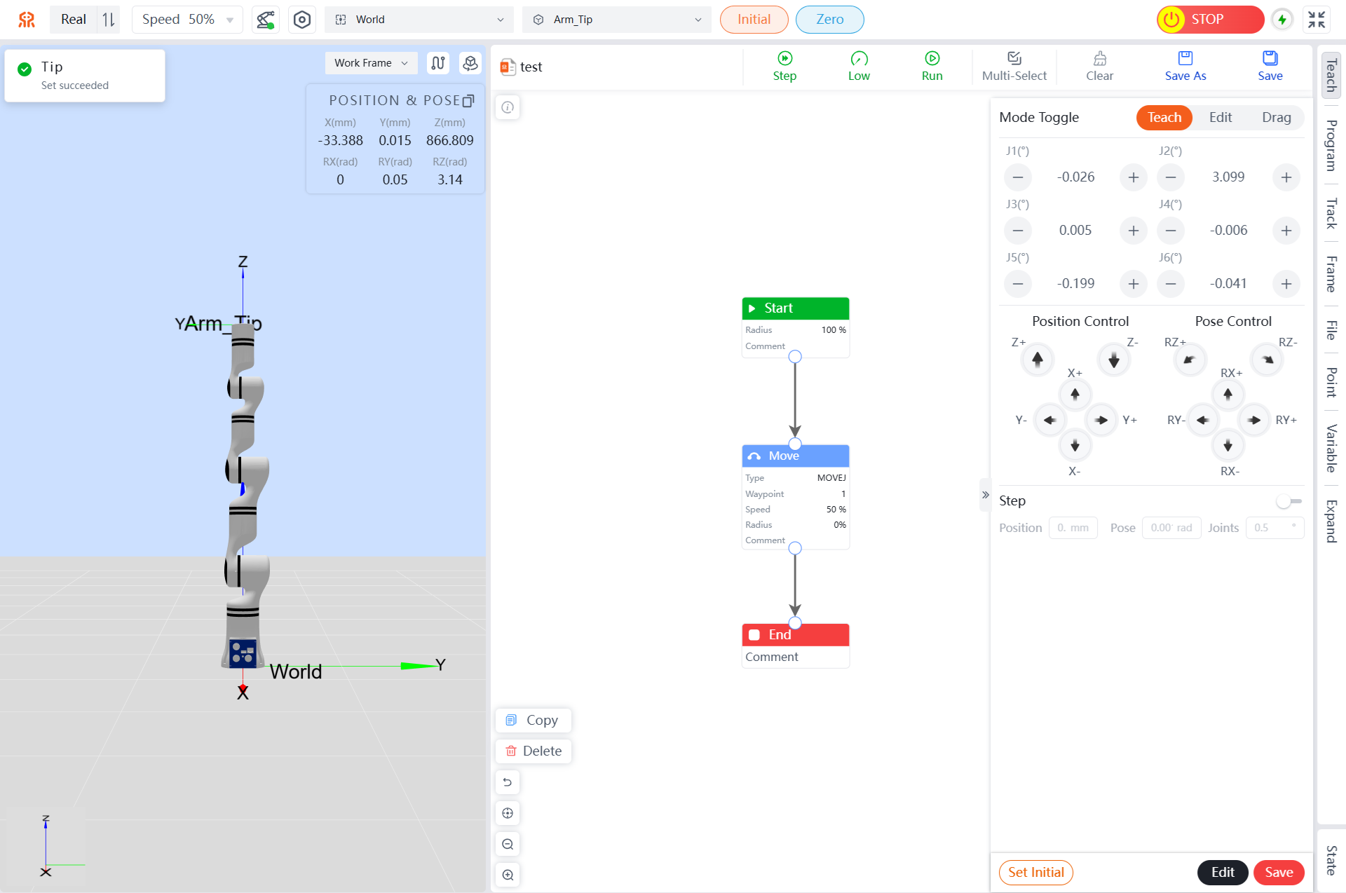
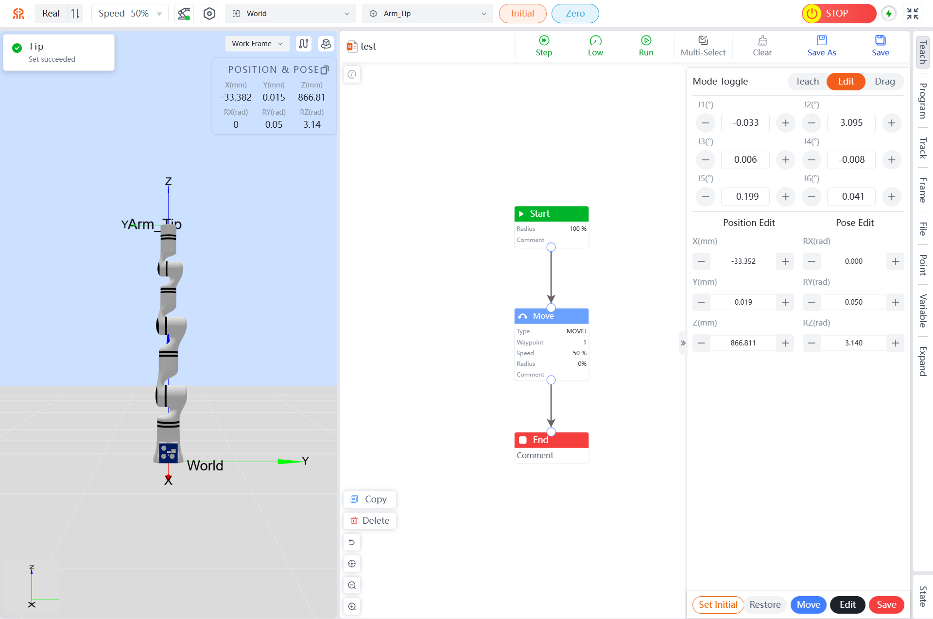
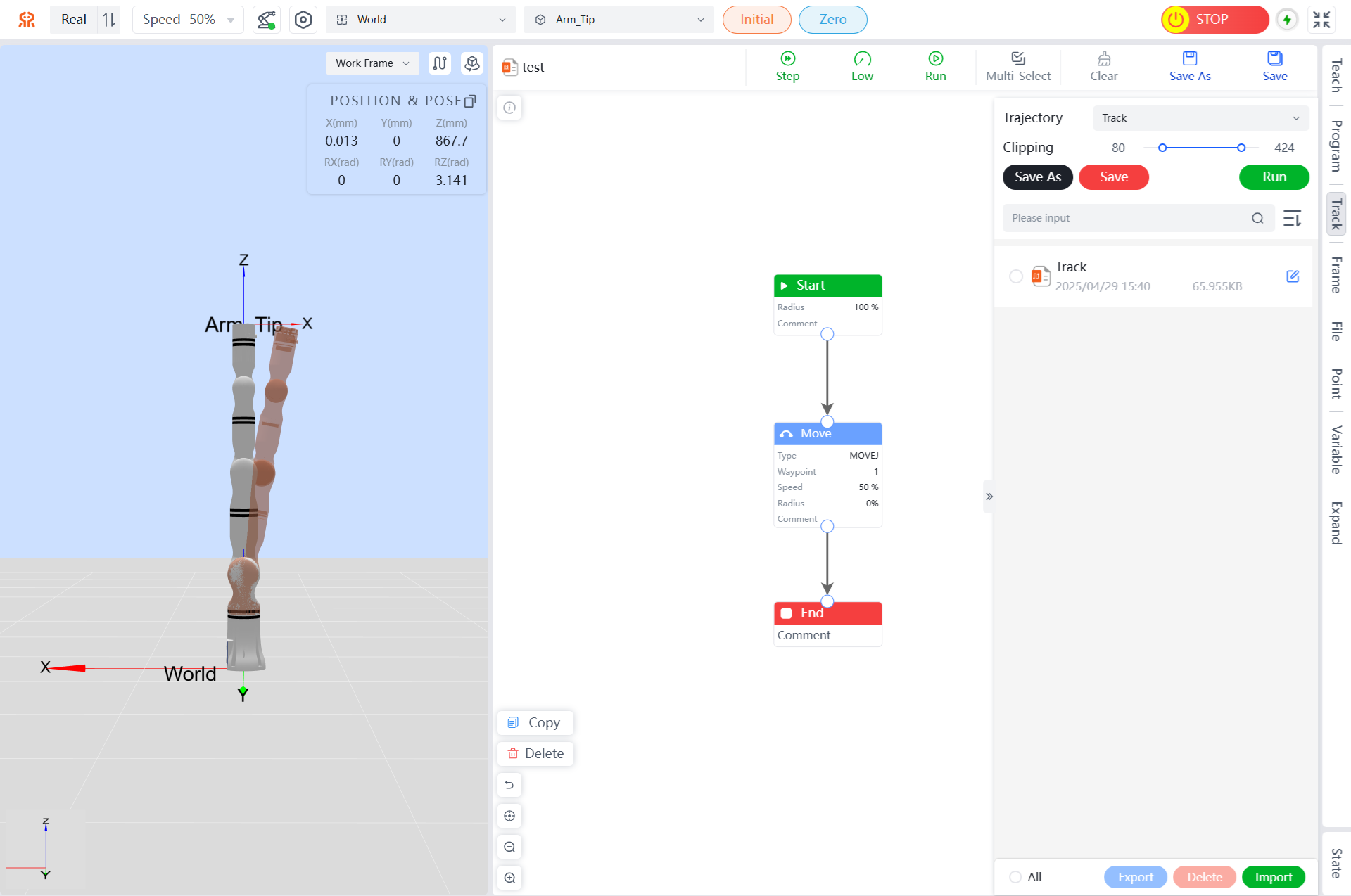
Graphical Programming Interface
| No. | Name |
|---|---|
| 1 | Current Program File Name |
| 2 | Step Button |
| 3 | Low Button |
| 4 | Run Button |
| 5 | Multi-Select Button |
| 6 | Clear Button |
| 7 | Save As Button |
| 8 | Save Button |
| 9 | Copy Button |
| 10 | Delete Button |
| 11 | Undo Button |
| 12 | Reset View Button |
| 13 | Zoom Out Button |
| 14 | Zoom In Button |
| 15 | Teach Menu |
| 16 | Programm Menu |
| 17 | Track Menu |
| 18 | Frame Menu |
| 19 | File Menu |
| 20 | Point Menu |
| 21 | Variable Menu |
| 22 | Expand Menu |
| 23 | State Menu |
TIP
In the programming area, clicking the description button in the upper left corner will display a brief description of the Get started with flowchart programming in 30 seconds. Users can quickly get started with flowchart programming based on the prompts.
The following sections will describe each area/button in the order listed in the table above:
Step Button
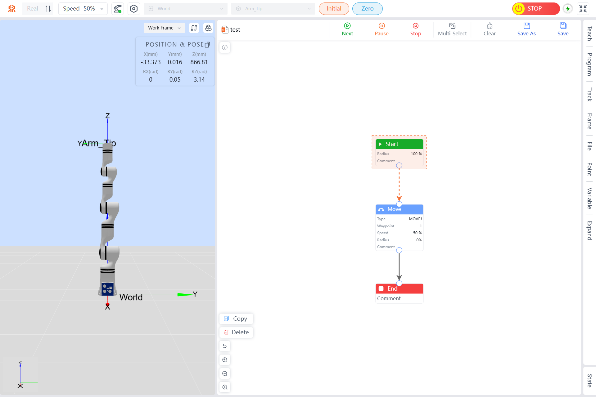
Online programming data can be executed step by step. Click the Step button, and the Step, Low, and Run buttons will change to Next, Pause, and Stop buttons, respectively. In step mode, the program executes one command at a time. Only after completing a segment of the trajectory, can you click the Next button to issue the command for the next segment of the trajectory.
Low Button
After an online programming project is established, click Low, and the Step, Low, and Run buttons will change to Pause and Stop buttons, respectively. During automatic trajectory execution, the background color of the current move programming point will turn bright.
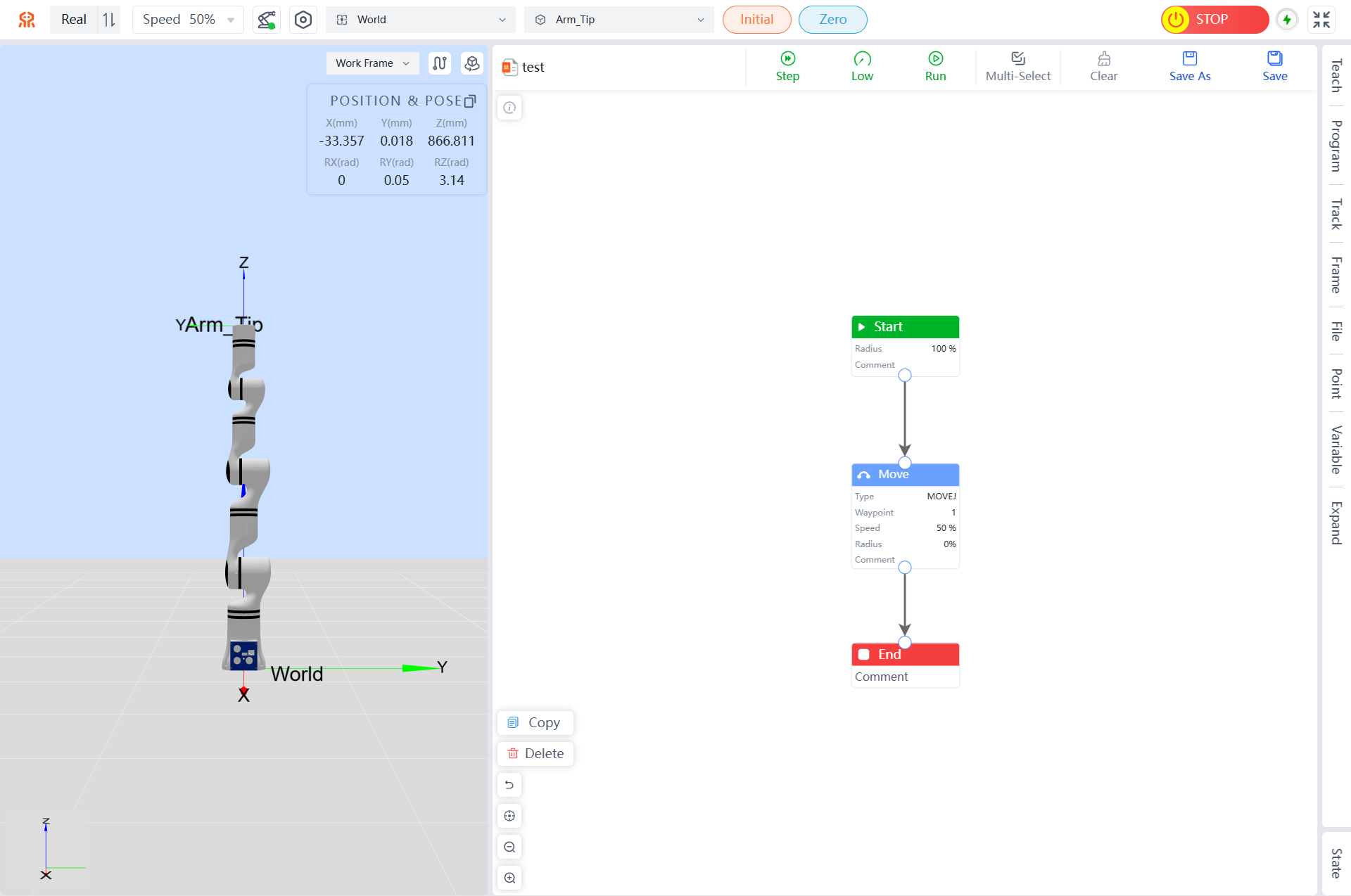

Run Button
After an online programming project is established, click the Run button, and the Step, Low, and Run buttons will change to Pause and Stop buttons, respectively. During automatic trajectory execution, the background color of the current move programming point will turn bright.


Pause Button
During robot movement, click the Pause button to immediately stop the robot's move. The Pause and Stop buttons will change to Stop and Continue buttons, respectively. When you click Continue again, the robot will continue moving.
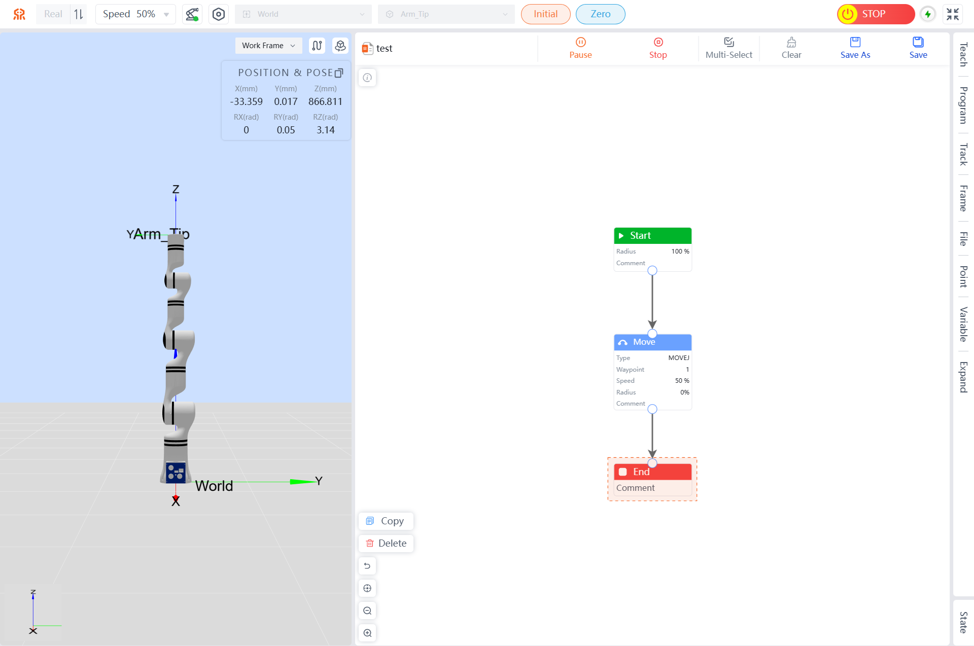
Stop Button
When you click the Stop button, debugging of the project will stop, and the operation buttons will revert to Step, Low, and Run. Clicking the Stop button will also stop the trajectory, and it cannot be continued.
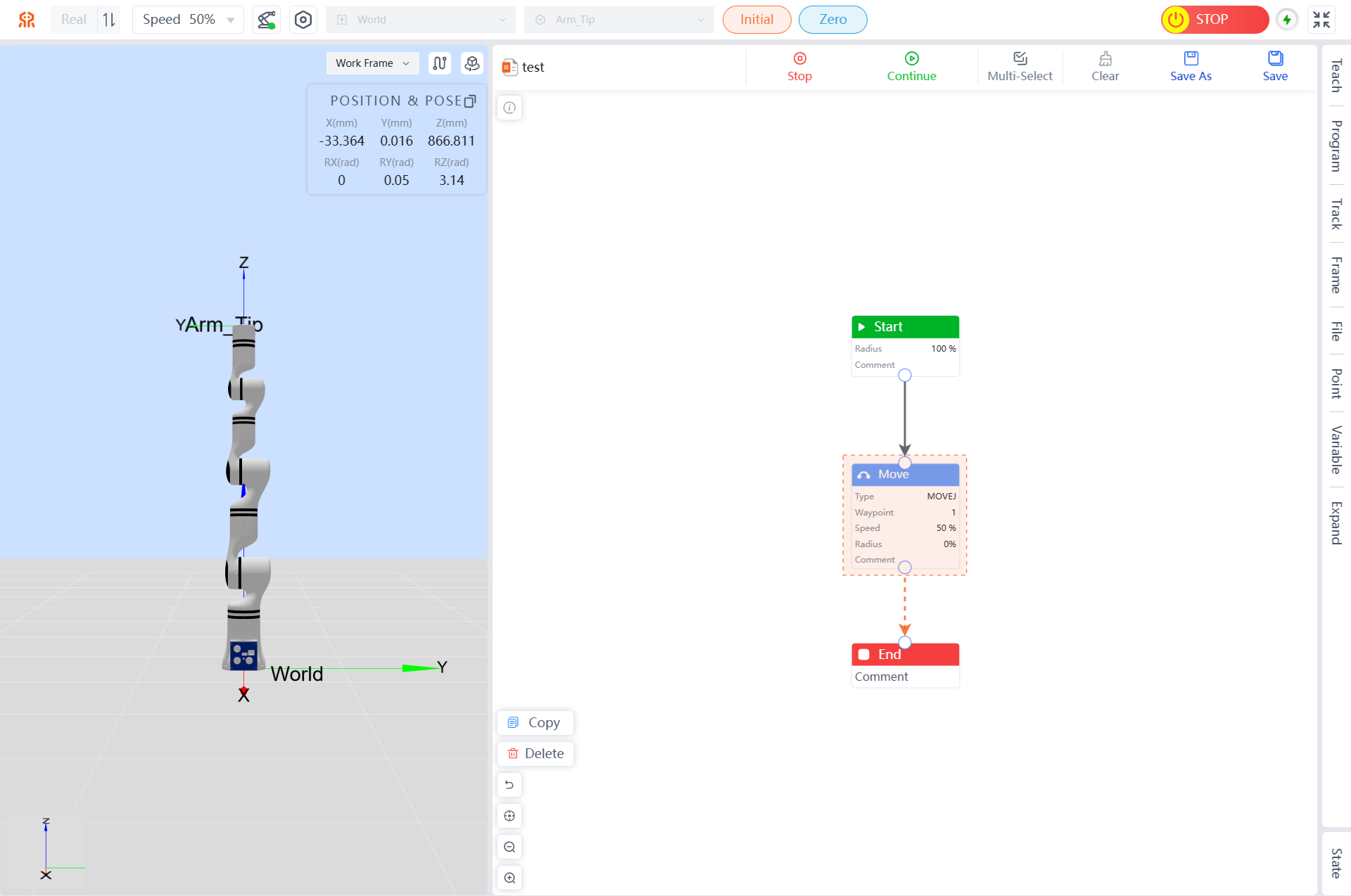
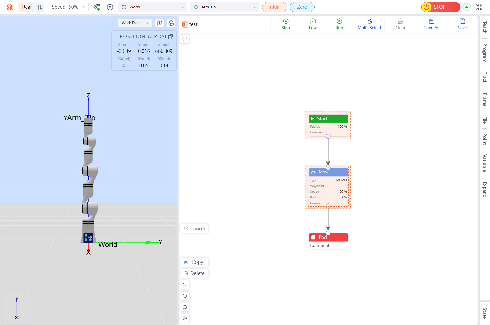
Multi-Select Button
When you click the Multi-Select button, a Cancel button will appear on the left side, allowing you to select multiple Command models for operations such as copy and delete. Clicking the Cancel button will exit multi-select mode.
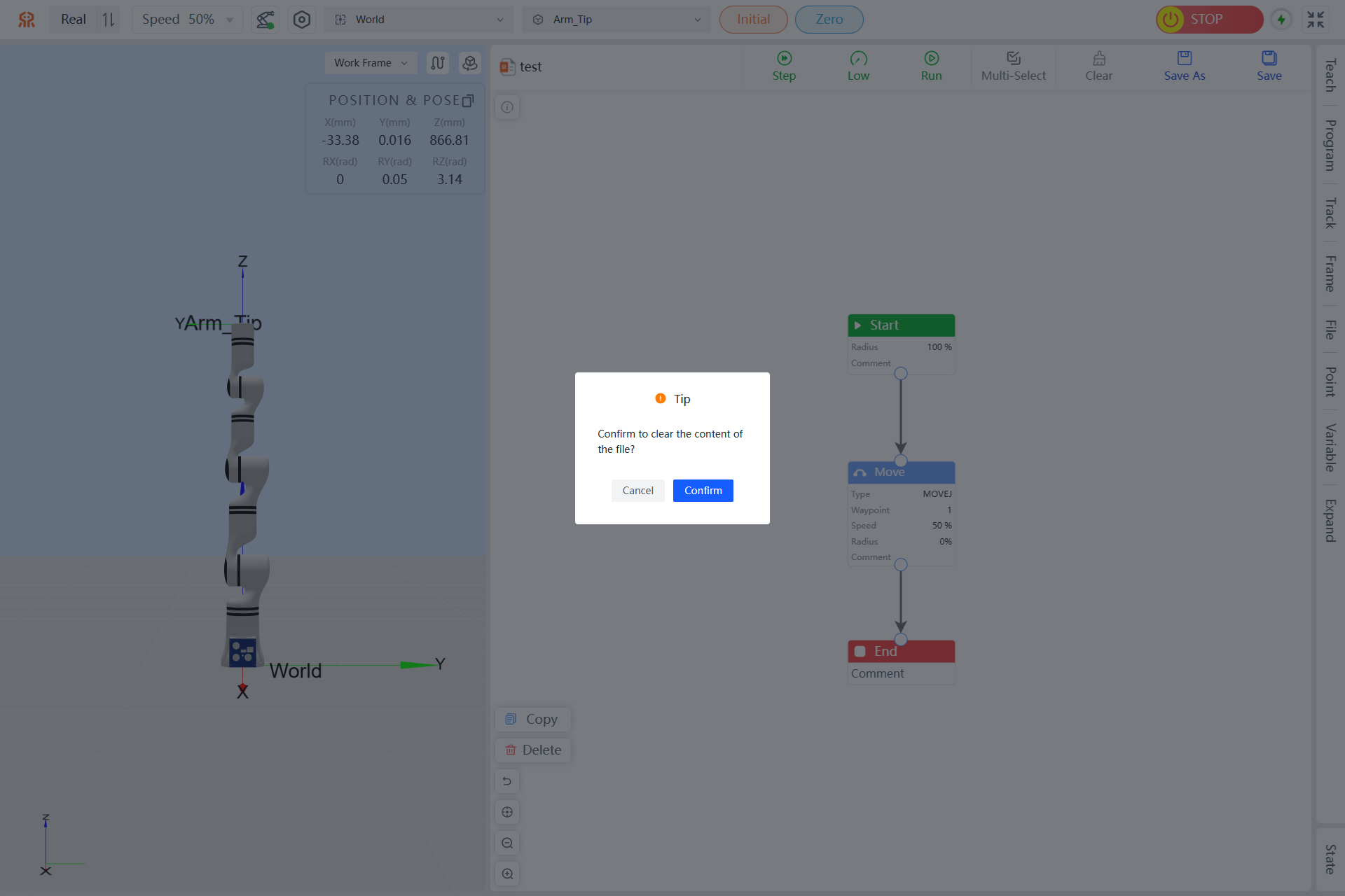
Clear Button
After clicking the Clear button, all models of the current project being edited will be cleared. If you confirm that you need to clear, click Confirm in the pop-up prompt box to clear. Click Cancel to abandon the clear operation.
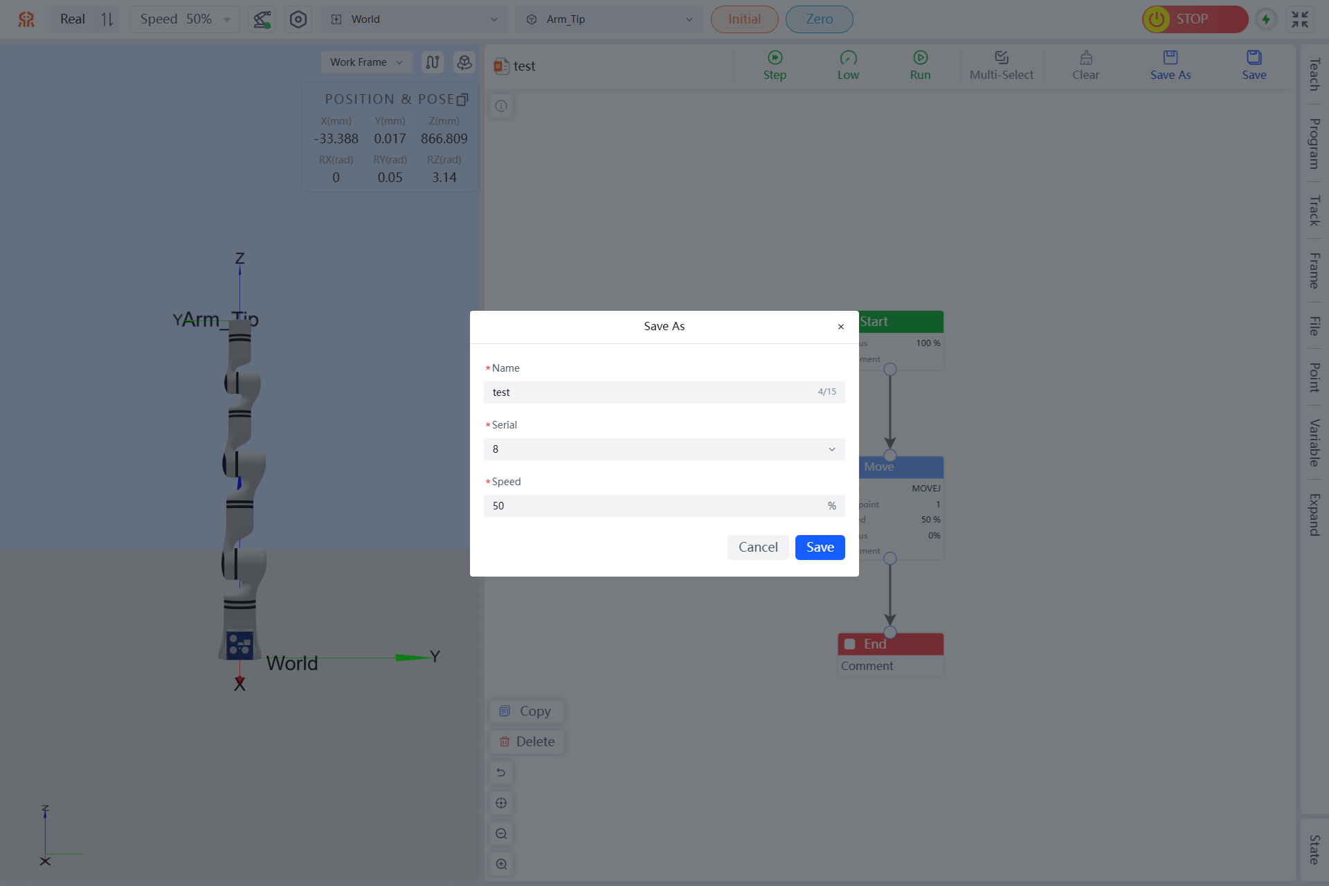
Save As Button
After writing and running a program in the graphical programming interface, you can save it as another file by clicking Save As. A pop-up window will appear where you can set the name, number, and speed of the programming file, then click Save. The saved programming file will be available in the file menu. The saved file can also be called directly via TCP or Modbus.
Save Button
After writing and running a program in the graphical programming interface, click Save. When a successful save prompt appears, it indicates that the save was successful. The saved programming file can be viewed in the file menu. The saved file can also be called directly via TCP or Modbus.
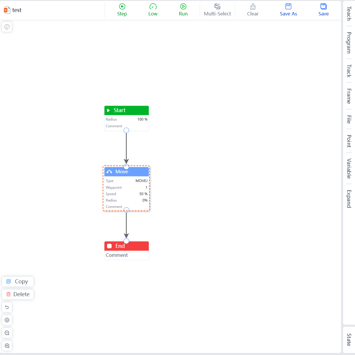
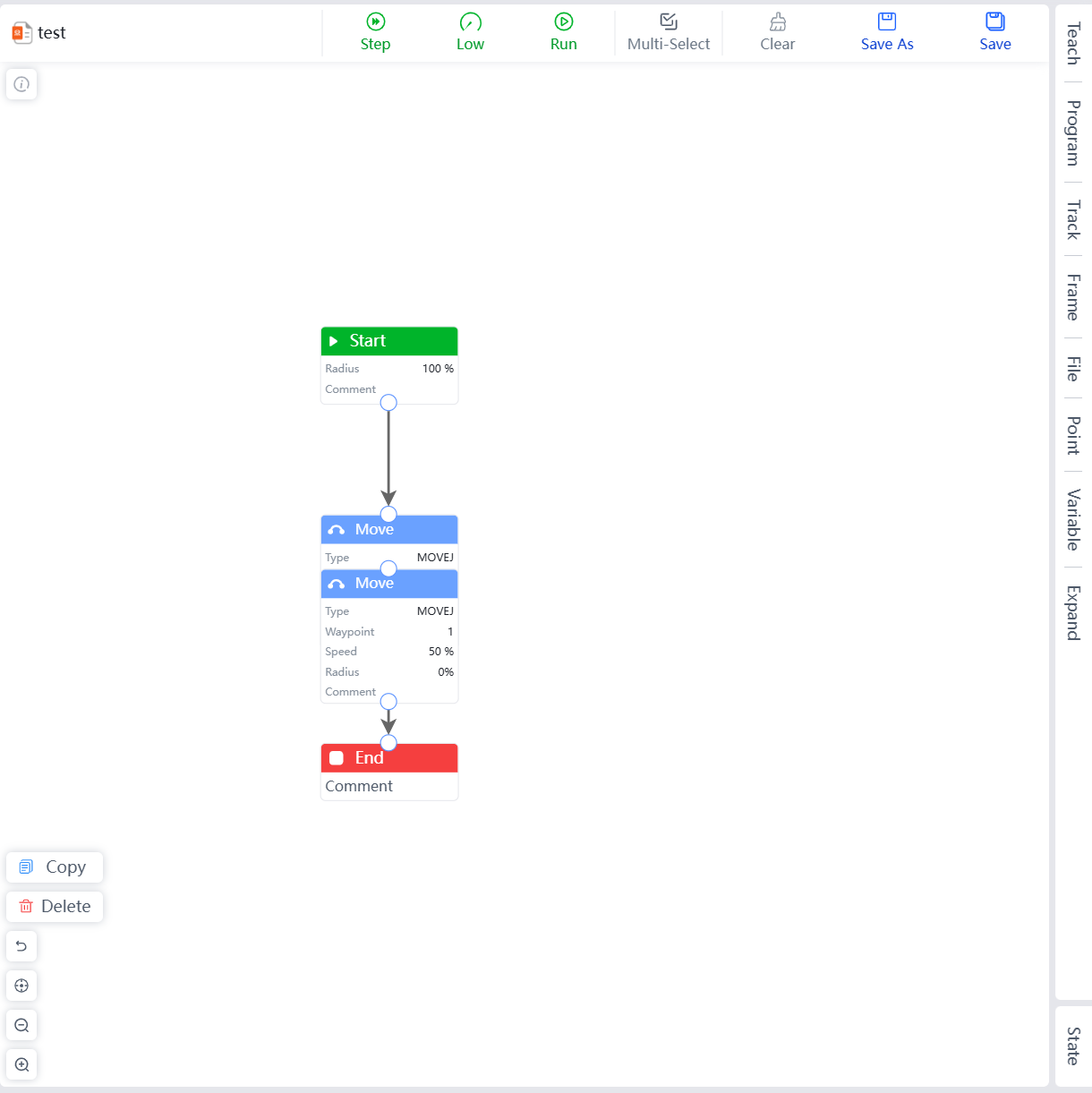
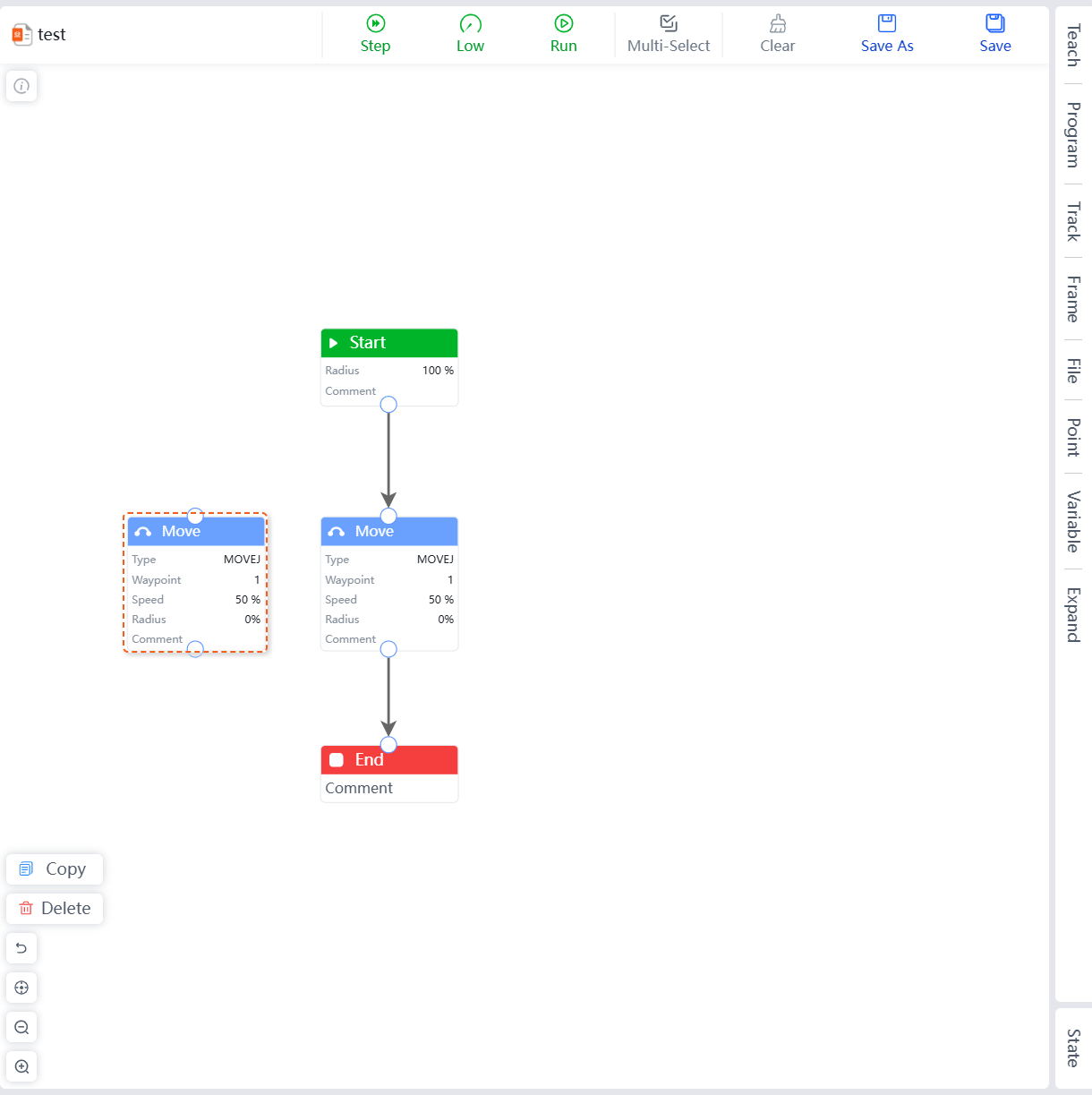
Copy Button
In the graphical programming interface, you can copy selected models (except the start module). Select the module to be copied, click Copy, and a new module will be automatically created based on the original module. Users can edit it as needed.
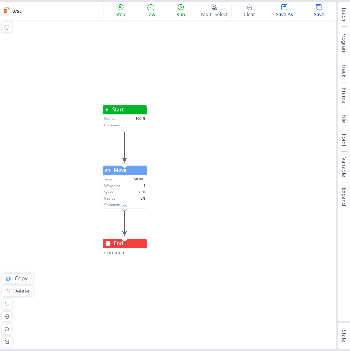
Delete Button
In the graphical programming interface, you can delete selected models. Select the module to be deleted, click Delete, and the selected module will be deleted.
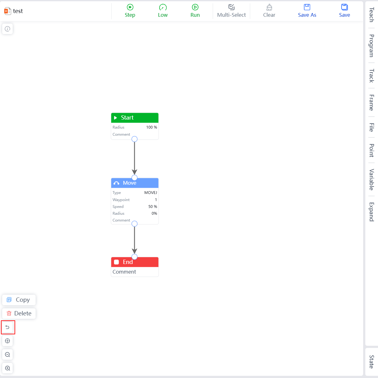
Undo Button
In the graphical programming interface, you can undo the last operation. Click the undo button to undo the last operation, and multiple consecutive undos are supported.
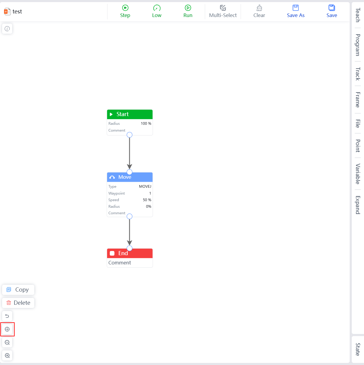
Reset View Button
In the graphical programming interface, you can reset the view of the editing interface. After clicking the reset view button, the system will automatically reset all models to the center of the editing interface.
Zoom Out Button
In the graphical programming interface, you can zoom out of the editing interface. After clicking the zoom out button, the system will reduce the size of the editing interface, showing a larger area of the editing interface.

Zoom In Button
In the graphical programming interface, you can zoom in on the editing interface. After clicking the zoom in button, the system will enlarge the editing interface to view detailed configuration information of the models.
Teach Menu
Three teach modes are supported: Teach, Edit, and Drag. The default mode is Teach.
Teach Mode
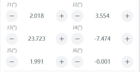
Joint Control
The robot has 6 degrees of freedom, with each joint from bottom to top named Joint 1 to Joint 6, corresponding to the six joints of the robot. Users can control the rotation of each robot joint using the joint control buttons on the teaching interface. Increase indicates increasing the angle of the joint, and Decrease indicates decreasing the angle of the joint, unit: degrees.
Button Table:
| Increase | Decrease |
|---|---|
 |  |
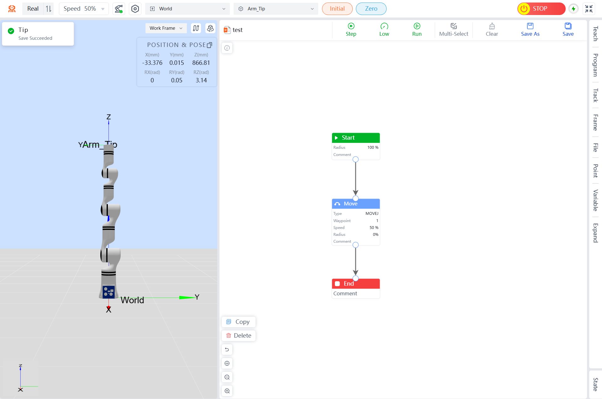
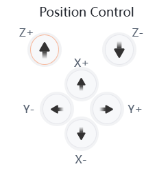
Position Control
The robot's end-effector can perform position control based on the world coordinate system (World), base coordinate system (Base), end-effector tool coordinate system (Arm_Tip), and user-defined plane coordinate systems. Users can teach the end-effector in different coordinate systems. For the X-axis, negative direction indicates movement in the negative X-axis direction, and positive direction indicates movement in the positive X-axis direction. Holding down the button causes the robot to move, and releasing it stops the robot. The same applies to other axes.
Button Table:
| Negative Direction | Positive Direction |
|---|---|
 |  |
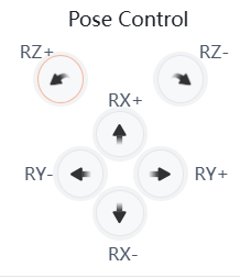
Pose Control
The robot's end-effector can perform pose control based on the world coordinate system (World), base coordinate system (Base), end-effector tool coordinate system (Arm_Tip), and user-defined work and tool coordinate systems. Users can teach the end-effector in different coordinate systems. During pose teaching, the end-effector's position remains unchanged, while the pose changes around the specified coordinate axis. For RX, negative direction rotation indicates rotation in the negative X-axis direction, and positive direction rotation indicates rotation in the positive X-axis direction.
Button Table:
| Negative Direction Rotation | Positive Direction Rotation |
|---|---|
 |  |
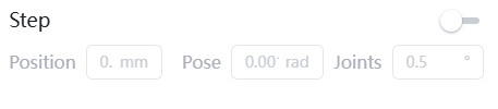
Step Mode Setting
To increase the precision of teaching, the step control mode is used, which allows the controlled variable to change precisely in steps.
- First, click the switch to the right of
Stepto enable step mode and enter step control. - Users can adjust the robot's movement by modifying the step size.
- Position: Indicates the distance the end-effector moves in the corresponding direction when a direction button is clicked once in the position control area, measured in millimeters (do not release the button during movement; releasing it will stop the movement mid-way).
- Pose: Indicates the angle of end-effector pose movement in the pose control area, with units selectable as radians (rad) or degrees (°).
- Joint: Indicates the angle of movement for the corresponding joint in the joint control area, measured in degrees (°).
TIP
Step control is only effective for end-effector control and joint axis control.
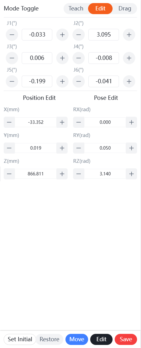
Edit Mode
- Adjust the angles of each joint of the robotic arm by modifying the joint angles or dragging the red virtual model's joints in the 3D simulation area.
- Fine-tune the joint angles and position/pose using the
+and-buttons. The adjusted position and pose of the robotic arm are represented by the red virtual model. - Holding down the
Movebutton causes the robotic arm to move to the position of the red virtual model, and releasing it stops the robotic arm. Clicking theRestorebutton restores the red virtual model to the same position as the real robotic arm.
Button Table:
| “+” and “-” Buttons | “Move” Button | “Reset” Button |
|---|---|---|
 |  |  |
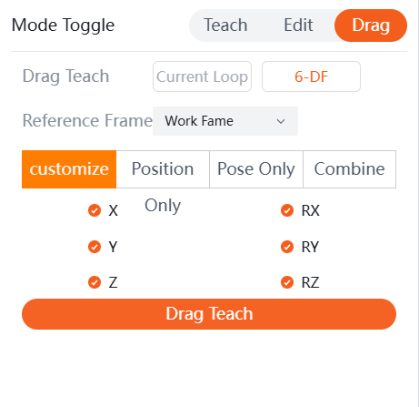
Drag Mode
Teaching Pendant Drag Teaching
In addition to recording points and running trajectories through the robot teaching interface, the robot also supports drag teaching.
Drag Teaching Settings Include:
- Current Loop Drag Teaching: After enabling current loop mode, any part of the robotic arm can be dragged to change its pose. Sensitivity can be set; higher values make dragging easier, while lower values make it harder.
- 6-DoF Drag Teaching: This drag mode is available only for 6-DoF versions of the robotic arm. Users can choose a reference Frame and support customize, position, pose, and combine drag modes. Users can also freely combine drag states for 6-DoF versions of the robotic arm.
- Reference Frame: Choose between work Frame and tool Frame as needed.
- Drag Method: Position allows movement through all axes without rotation; pose allows spherical movement around the TCP (Tool Center Point) through all axes; combined allows movement through all axes with all axes being free.

Drag Teaching Operation Method:
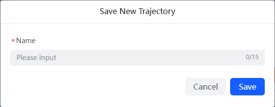
On the teaching pendant, click the Drag Teach button, then drag the robot. After completing, click Stop to record the trajectory, and a window will pop up to save the new trajectory file based on your needs.
| Start Drag Teaching | Complete Drag Teaching |
|---|---|
 |  |
After the path recording is completed, click the blue button at the end of the robot to replay the path.
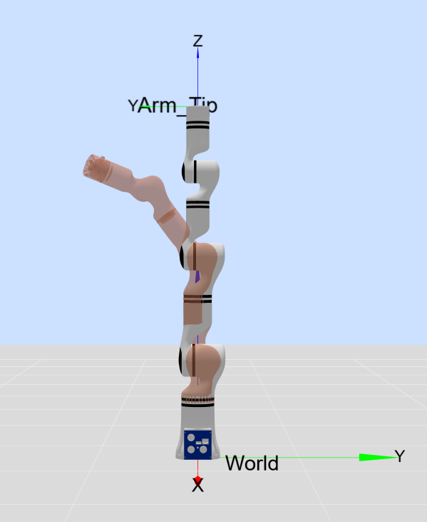
End Effector Button Drag Teaching
There are two buttons on the end effector flange of the robotic arm, each controlling the robot for drag teaching and path replay.
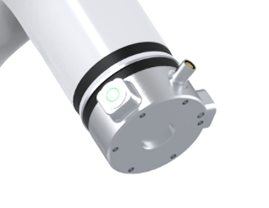
Hold the green button at the end of the robotic arm, and the robotic arm will be in a draggable state. Drag the end of the robotic arm to record the path, and release the green button to complete the path recording. The position of the end effector button is shown in the figure below.
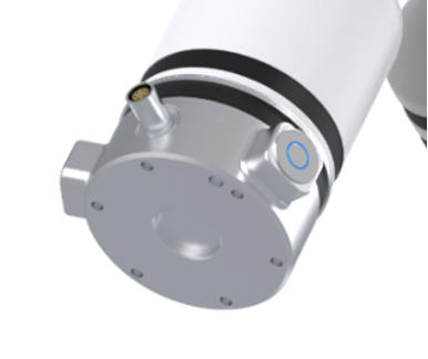
Click the blue button at the end of the robotic arm, and the robotic arm will automatically return to the starting position of the path and replay the path (the robotic arm only replays the last recorded drag path).
Setting Initial Pose
The robot can set an initial pose, making it convenient for users to quickly control the robot to reach that pose.
The current teaching pendant supports setting the initial pose of the robotic arm in teaching mode or editing mode.
- Teach Mode: After entering teaching mode, refer to Teach Mode to modify joint and pose parameters, then click
Set Initialto complete the initial pose setting. - Edit Mode: After entering editing mode, refer to Edit Mode to modify joint and pose parameters, then click
Set Initialto complete the initial pose setting.
Programming Menu
Examples
The teaching pendant provides several programming examples for users to use as needed.
| No. | Example Name | Description |
|---|---|---|
| 1 | Walk Straight | Example of the robotic arm moving in a straight line. |
| 2 | Draw Circle | Example of the robotic arm drawing a circle. |
| 3 | Draw 8 | Example of the robotic arm drawing a figure eight. |
| 4 | Running In | Example of the robotic arm running-in with limits. |
| 5 | Force Control | Example of the robotic arm operating with force control. |
Model
Models are the base Command units for graphical programming, including seven categories: Base, Move, Control, IO, Modbus, Ecology, Trajectory, and Force Control.
Double-click an added module allows you to set parameters for the target module in the settings tab.
Node Function Overview
| Node | Function Description |
|---|---|
| Motion | The motion module provides multiple instruction types such as joint motion (MoveJ/MoveJ_P), linear motion (MoveL), circular motion (MoveC), and spline motion (MoveS). It allows configuration of waypoints, speed, and transition parameters to plan various motion trajectories for the robotic arm. |
| Offset | The offset module controls the end-effector of the robotic arm to perform precise linear offsets along the X, Y, and Z axes based on the specified tool or user coordinate system. It allows setting the offset amount for each axis, movement speed, and blend radius, and choosing whether to block subsequent instructions to ensure motion completion. |
| Wait | The wait module is used to create a configurable pause in the process. You can manually input a time or select a variable to set the waiting duration. The program will block here until the time elapses before executing subsequent instructions. |
| Wait IO | The wait IO module pauses the program, waiting for a specified digital input signal to reach a preset level state. |
| Wait Modbus | The wait Modbus module pauses the program, waiting for the data read from a device register via a specified Modbus connection (such as TCP, RTU, or robotic arm slave) to meet a preset condition. It allows configuration of protocol type, device address, register address, and expected data. The program will block here until the condition is met. |
| Condition | The condition module performs logical judgment based on a set conditional expression to control the branching direction of the program flow. It allows configuration of operands, comparison operators (such as equal, greater than), and judgment values. Both operands and judgment values support manual input or variable binding, enabling dynamic conditional judgment. |
| Calculation | The calculation module is used to perform mathematical operations, evaluating expressions composed of constants/variables and operators, and saving the result to a target variable for subsequent instructions to call, enabling dynamic numerical calculation and transfer within the program. |
| Popup | This module is used to pop up a prompt window during program runtime, displaying custom titles and remarks. This operation is in blocking mode; the program will pause execution until the user confirms and closes it, thus achieving real-time notification of critical information and process control. |
| Read IO | The read IO module is used to read the current level state (high/low) of a specified digital input port (such as DIN1) in real-time, and store this state value into a specified variable for subsequent logical judgment or data processing. |
| Set IO | This module is used to control the level state of a specified digital output port (such as DOUT1), setting it to high or low level, thereby directly driving the on/off of external devices. |
| Read Modbus | The read Modbus module reads data from a device register via a specified Modbus connection (TCP, RTU, or robotic arm slave). It allows configuration of the device address, register address (supporting variables), and read length, and stores the read result into a specified variable for subsequent data processing and logical judgment. |
| Write Modbus | The write Modbus module writes data to a device register via a specified Modbus connection (TCP, RTU, or robotic arm slave). It allows configuration of the target device, register address, data length, and the data to be written, used for controlling external devices or configuring parameters. |
| End Tool | After enabling the RM_ARM+ protocol in the teach pendant extension interface to automatically obtain end-effector device information, the target angle or position for controlling the gripper/dexterous hand can be stored as an action. This module is used to directly call these pre-stored actions in graphical programs, and can set blocking or non-blocking execution modes. |
| Lifter | The lifter module is used to control an enabled lifting mechanism to move to a specified target height. You can manually input or set the target height and movement speed via variables, and select blocking or non-blocking execution mode. (Note: Ensure the lifting mechanism function is enabled before use.) |
| Trajectory | The trajectory module is used to call and execute a complete motion trajectory pre-recorded and saved via drag teaching. You can directly select the trajectory name and set it to play back the entire path in blocking or non-blocking mode. |
| Force Control | The force control module provides complete six-dimensional force control functionality. It allows setting force control mode, target force, and linear velocity for X, Y, Z directions, while also setting torque control mode, target torque, and angular velocity for MX, MY, MZ directions, thus enabling precise compliance operations such as precision assembly or surface grinding. |
| Force Control Stop | The force control stop module is used to make the robotic arm exit force control mode and restore to the default rigid position control state. This operation is instantaneous and does not block subsequent instructions. |
| Pallet | By setting the pallet origin, row and column layout, and spacing, it automatically plans and generates a set of coordinate data for all points on the entire pallet, serving as the foundation for pallet motion. |
| Pallet Motion | According to the specified row and column indices, it precisely retrieves and executes the corresponding point coordinates generated by the pallet module, driving the robotic arm to complete positioning and operations within the pallet grid. |
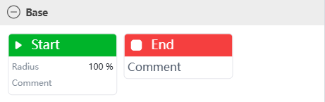
Base Commands
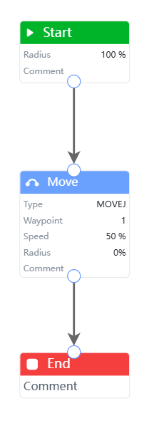
Base Commands include "Start" and "End" commands.
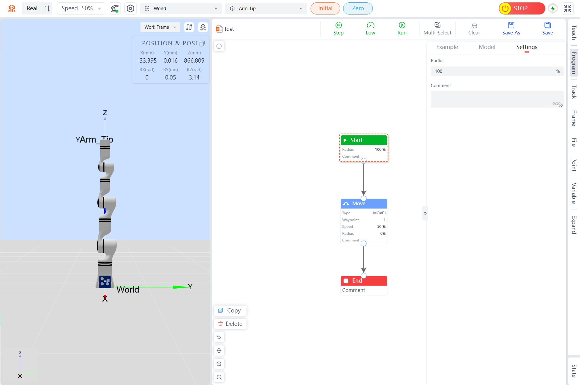
Start Command
"Start" is a module that must be added for each programming session, placed at the beginning of the program. If this module is not added, a pop-up message will appear at the top of the teaching pendant interface saying "Missing Start Module."

Radius: Enter the required blend radius range; the default value is 100%. If not needed, do not change it.
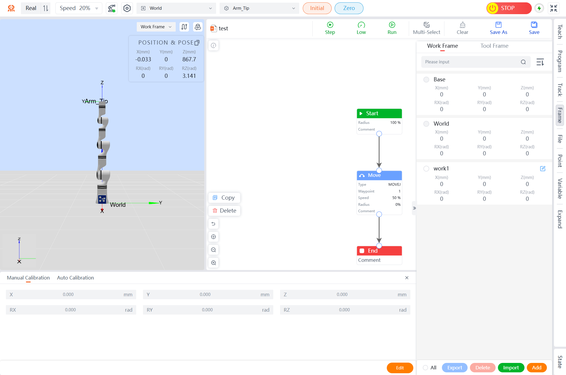
Program Example: Set the blend radius of the start Command to 100%, as shown in the following figure.
End Command
"End" ends the program when it reaches the termination command.
Move Commands
Move Commands include "Move" and "Offset" commands.
Move Commands
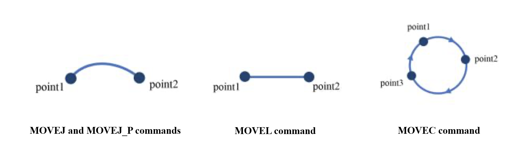
Move commands are divided into five types of move: "MOVEJ", "MOVEL", "MOVEC", "MOVES", and "MOVEJ_P".
- MOVEJ and MOVEJ_P commands: Only ensure the final waypoint position, without constraining the intermediate trajectory.
- MOVEL command: While ensuring the final waypoint position, it guarantees that the trajectory between two points is a straight line.
- MOVEC command: Used to execute arc or circular trajectories, only two waypoints (intermediate point and endpoint) can be added.
- MOVES command: Can achieve more complex curve movements, no consecutive points can have the same position.
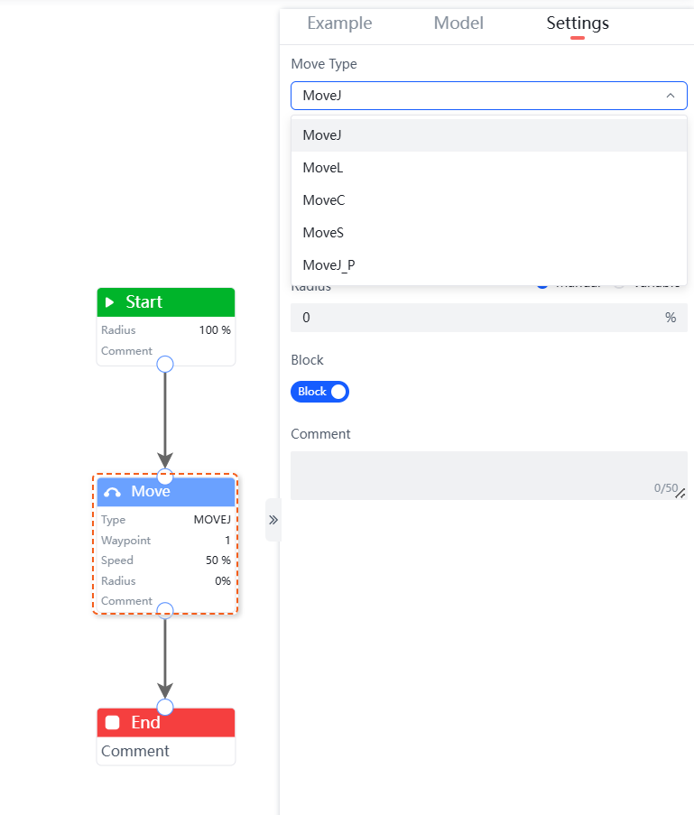
The "Move" command can set the Move Type, Point, Speed, Radius, and Block.
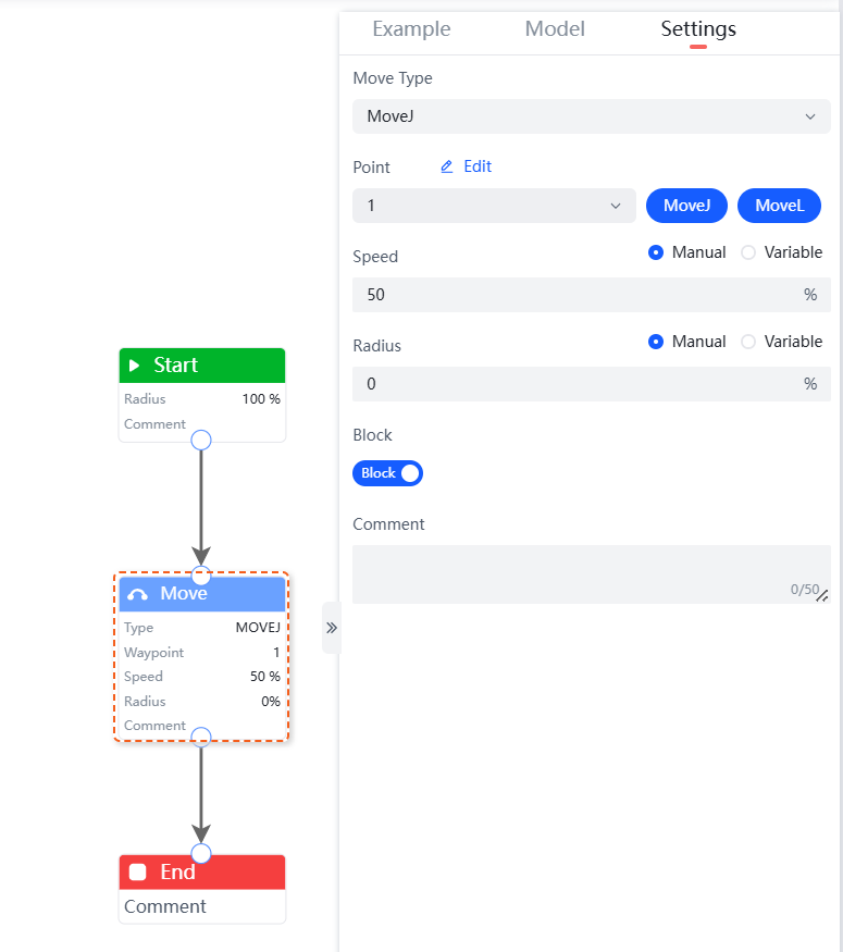
Move Type: Includes "MOVEJ", "MOVEJ_P", "MOVEL", "MOVEC", and "MOVES", which represent joint move, linear move, arc move (when the number of circles is "0", it executes an arc trajectory; when the number of circles is greater than or equal to 1, it executes a circular trajectory), and curve move. Both "MOVEJ" and "MOVEJ_P" are joint moves, but they have different waypoint parameters. The waypoint parameters for "MOVEJ" are the angles of each joint axis, while "MOVEJ_P" is the pose of the tool coordinate point.
point: Users can select saved waypoints from the dropdown menu as the robot's working move points. This command can select waypoints saved in advance. After selecting a waypoint, the following operations can be performed.
- By clicking the edit button, you can jump to
Teach>Editto edit the waypoint. For more details, refer to Point Menu. - By clicking the
MoveJorMoveLbutton to the right of the waypoint, you can debug the robot's movement to that point, which only affects the current "waypoint".- In the settings panel on the right, select the target point and hold down the
MoveJbutton to control the robot to move to the target point in MOVEJ form from its current position. Release the button to stop the movement. - In the settings panel on the right, select the target point and hold down the
MoveLbutton to control the robot to move to the target point in MOVEL form from its current position. Release the button or when an unreachable situation occurs, the movement stops.
- In the settings panel on the right, select the target point and hold down the
- By clicking the edit button, you can jump to
Speed: This is the default speed for waypoints under this move command, and it can be set through manual input or by selecting a manually added variable.
Radius: The default is 100%, no change is required, but it can be set through manual input or by selecting a manually added variable.
Block: Divided into blocking and non-blocking modes. In blocking mode, after the current move reaches its position, the robot executes subsequent commands; in non-blocking mode, during the current move, the robot simultaneously executes subsequent programs.
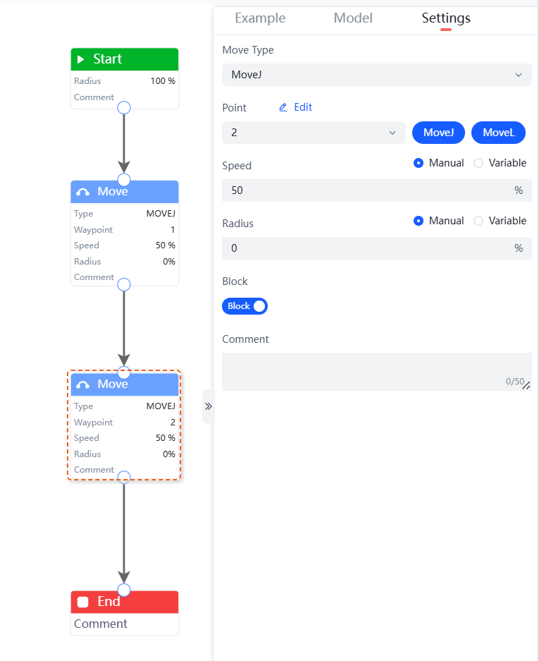
Program Example 1: Add a MOVEJ move trajectory in the program segment, where the move between Waypoint 1 and Waypoint 2 is MOVEJ. The example is shown in the following figure.
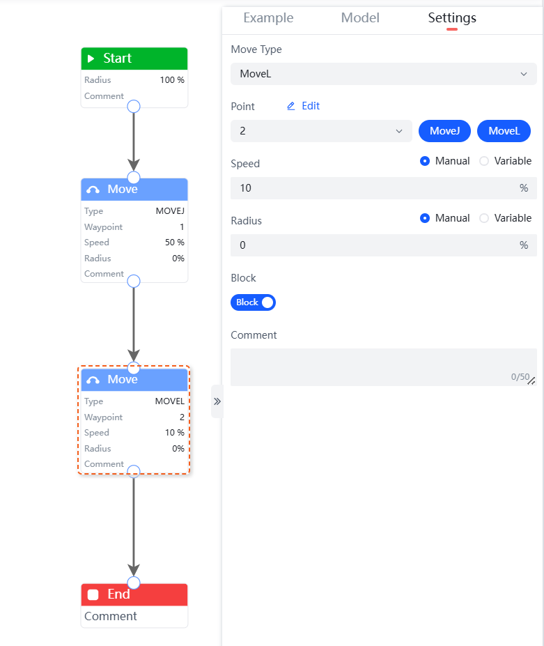
Program Example 2: Add a MOVEL move trajectory in the program segment. The example is shown in the following figure.
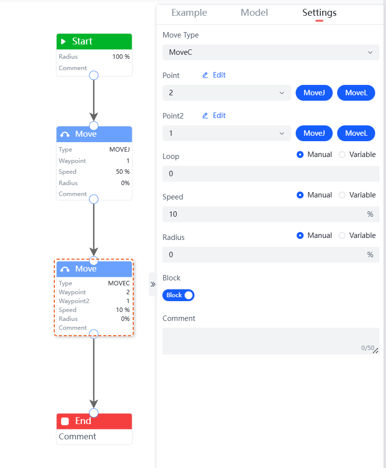
Program Example 3: Add a MOVEC move trajectory in the program segment. The example is shown in the following figure.
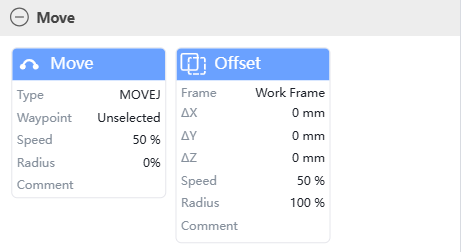
Offset Command
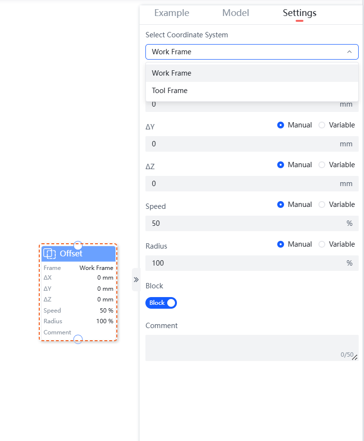
The offset command can set offsets based on two types of Frames: "Work Frame" and "Tool Frame".
The "Offset" command supports setting the coordinate system, ∆X, ∆Y, ∆Z, speed, radius, and block.
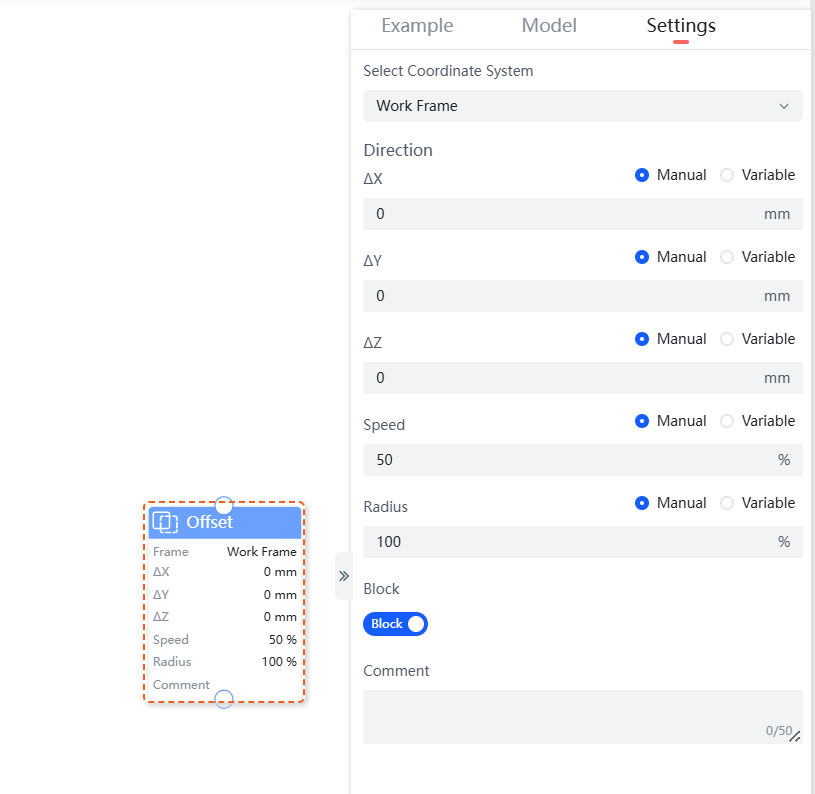
- Select Coordinate System: Includes "Work Frame" and "Tool Frame," representing offsets in the work Frame or tool Frame.
- Direction: Indicates the offset of the Frame.
- ∆X: Represents the offset amount on the X-axis, which can be set through manual input or by selecting a manually added variable. The unit is mm.
- ∆Y: Represents the offset amount on the Y-axis, which can be set through manual input or by selecting a manually added variable. The unit is mm.
- ∆Z: Represents the offset amount on the Z-axis, which can be set through manual input or by selecting a manually added variable. The unit is mm.
- Speed: Represents the default speed percentage for waypoints under this move command, which can be set through manual input or by selecting a manually added variable.
- Radius: The default is 100%, no change is required, but it can be set through manual input or by selecting a manually added variable.
- Block: Divided into blocking and non-blocking modes. In blocking mode, after the current offset reaches its position, the robot executes subsequent commands; in non-blocking mode, during the current offset, the robot simultaneously executes subsequent programs.
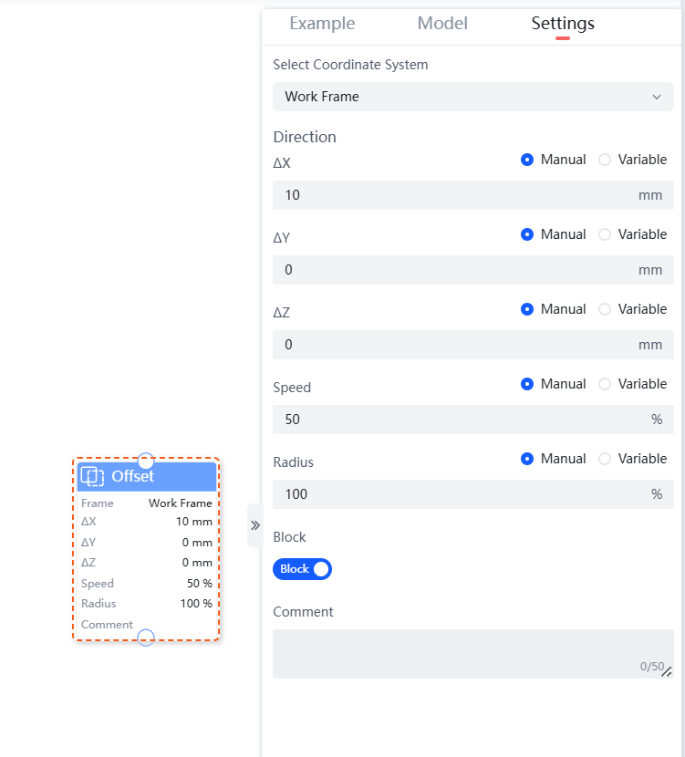
Program Example: Add an X-axis offset of 10mm in the program segment. The example is shown in the following figure.
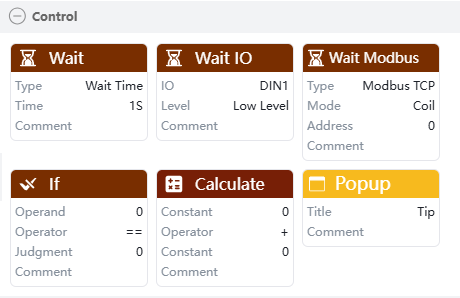
Control Commands
Control commands include six commands: "Wait," "Wait IO," "Wait Modbus," "If," "Calculate," and "Popup."
Wait Command
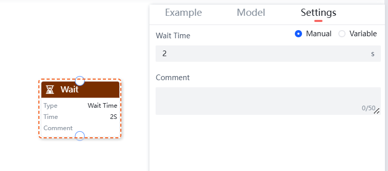
The "Wait" command is used for time setting and can set a wait time.
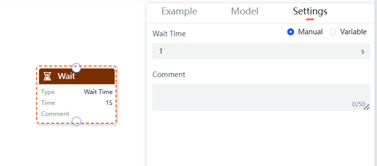
Wait Time: Users can set the waiting time, unit: s.
Program Example: Add a 2-second wait command in the program segment, as shown in the figure below.
Wait IO Command
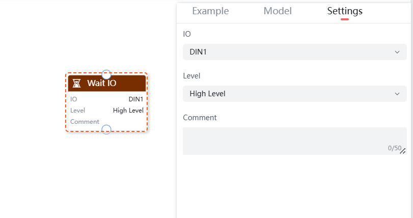
The "Wait IO" command is used to wait for signal input. You can set the waiting IO and level.
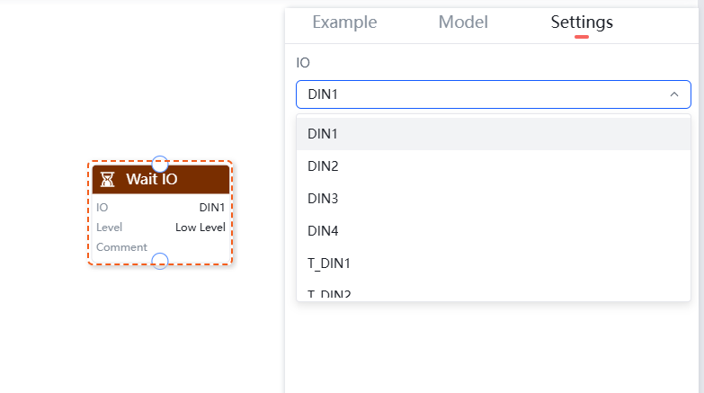
Wait IO: Wait for the IO interface to meet the set conditions. This includes digital input interfaces DIN1, DIN2, DIN3, DIN4 on the controller side and digital input interfaces T_DIN1, T_DIN2 on the tool side.
Level: Divided into high level and low level.
Program Example: Add a high-level command for IO DIN1 in the program segment, as shown in the figure below.
Wait Modbus Command
The Wait Modbus command is divided into three types: "Modbus TCP", "Modbus RTU", and "Robot Slave".
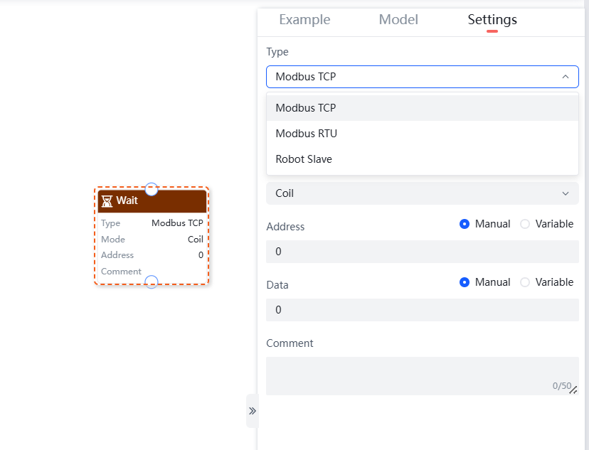
Different types of "Wait Modbus" commands support the following parameter settings:
- Modbus TCP: Supports selecting a device, register type, and setting the address and data.
- Modbus RTU: Supports selecting a device, register type, and setting the peripheral device address, address, and data.
- Robot Slave: Supports selecting a register type and setting the address and data.
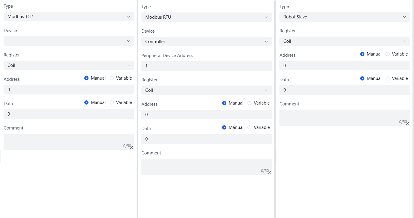
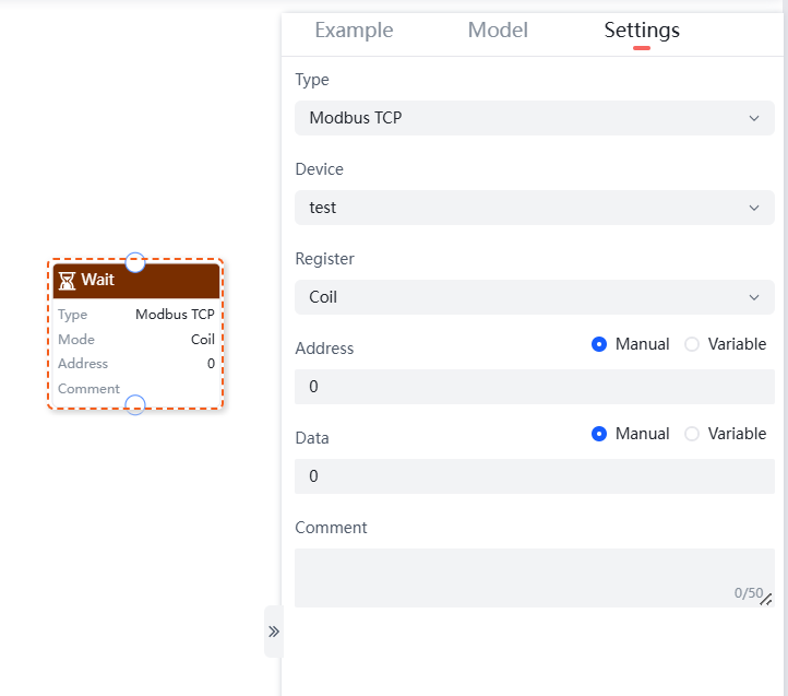
- Type: Choose the type of Wait Modbus command based on your needs, supporting Modbus TCP, Modbus RTU, and Robot Slave.
- Device: Automatically adapts to available devices based on the selected type.
- Peripheral Device Address: Enter the peripheral device address.
- Register: Select the register type, supporting Coil, Discrete Input, Holding Register, and Input Register.
- Address: Set the address for the Wait Modbus command, supporting manual input or selecting manually added variables.
- Data: Set the data for the Wait Modbus command, supporting manual input or selecting manually added variables.
Program Example: Add a Wait Modbus command of type Modbus TCP in the program segment, as shown in the figure below.
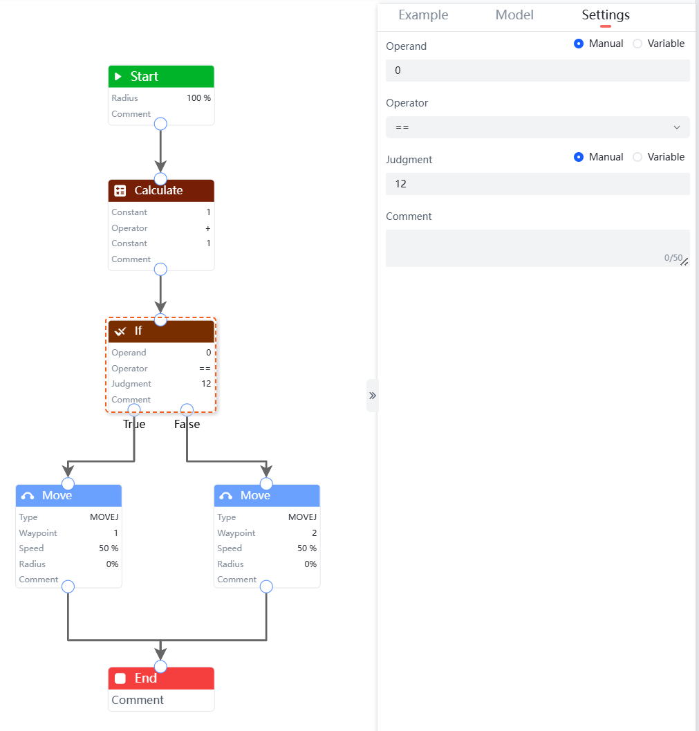
If Command
The "If" command is used to determine which branch of the program to execute. If the set conditions are met, the specified branch program is executed; otherwise, another branch program is executed.
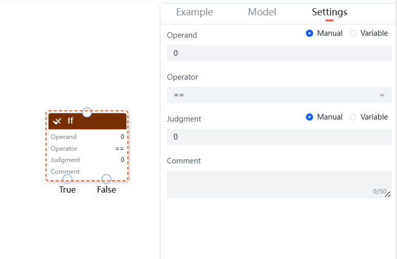
- Operand: Set the operand for the If command, supporting manual input or selecting manually added variables.
- Operator: Set the operator for the If command, supporting ==, !=, >, >=, <, <= six operators.
- Judgment: Set the judgment value for the If command, supporting manual input or selecting manually added variables.
Program Example: Add a If command in the program segment, as shown in the figure below.
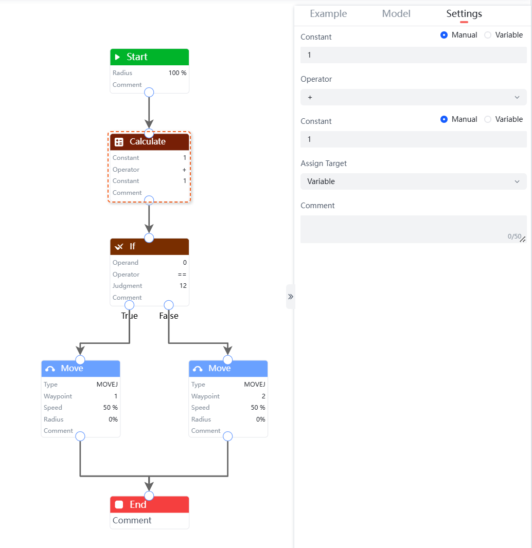
Calculate Command
The "Calculate" command is used to perform operations on constants or variables. It supports +, -, *, and /.
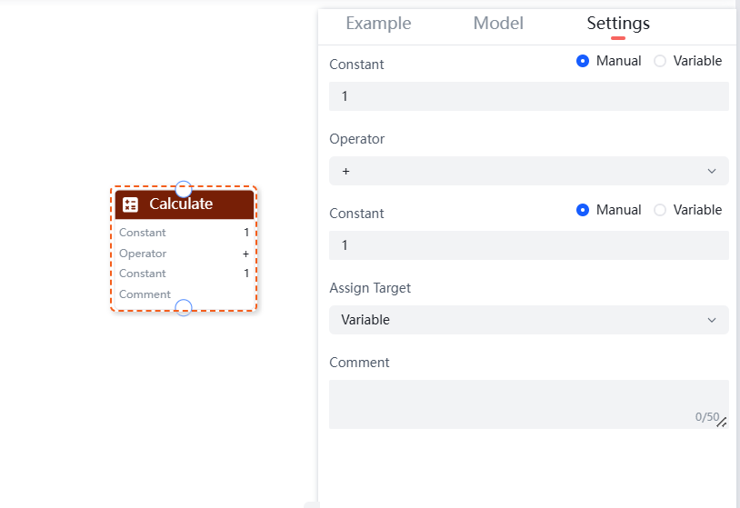
- Constant/Variable: Set the operand for the calculate command, supporting manual input or selecting manually added variables.
- Operator: Set the operator for the calculate command, supporting +, -, *, and /.
- Constant/Variable: Set the value for the calculate command, supporting manual input or selecting manually added variables.
- Assign Target: Choose the target for assigning the result of the calculate, only supporting variables that have been added as assignment targets.
Program Example: Add a calculate command in the program segment, as shown in the figure below.
Popup Command
The "Popup" command is used to provide information prompts to users. The pop-up content supports up to 15 characters.
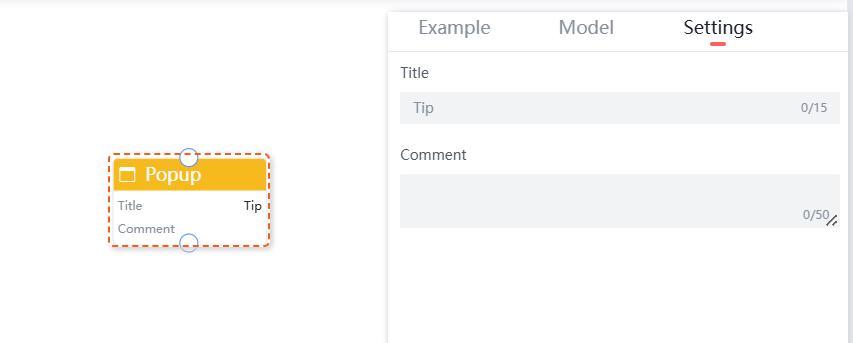
Program Example: Add a popup command in the program segment as shown in the figure below:
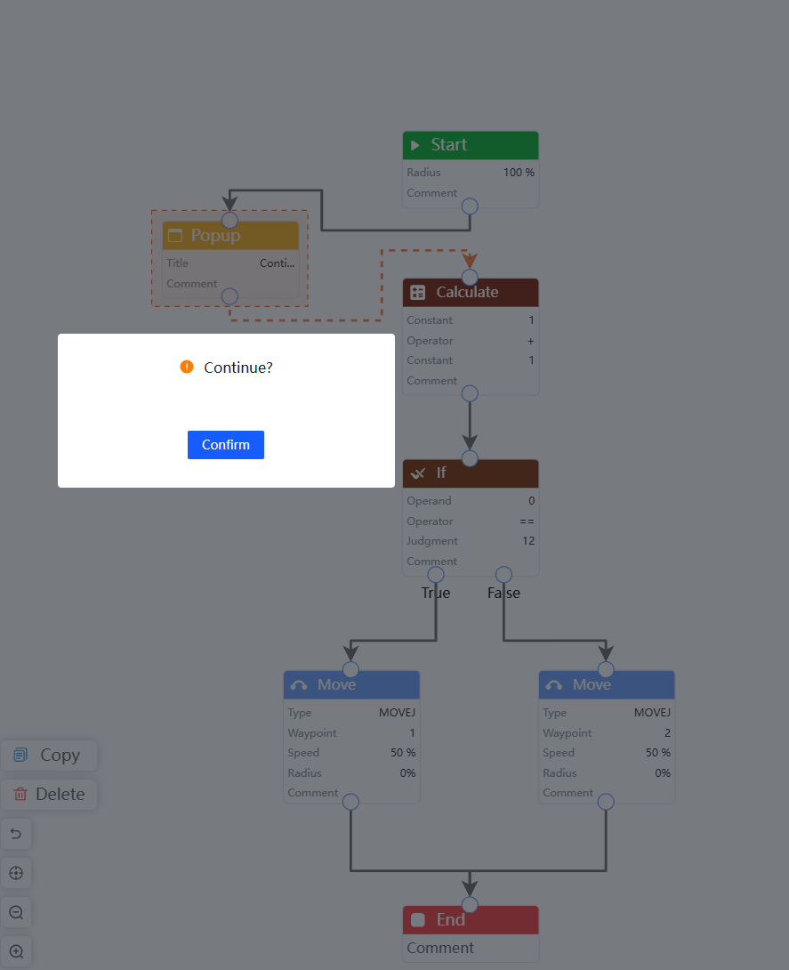
The program continues to execute after confirmation according to the prompt.
IO Command
The IO command includes two commands: "IO Input" and "IO Mode".
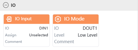
IO Input
The "IO Input" command is used to read the input level (high or low) of the controller IO (DIN1, DIN2, DIN3, DIN4) or the end-effector IO (T_DIN1, T_DIN2) and assign it to a variable.
This can be used to read the input level of the controller IO (DIN1, DIN2, DIN3, DIN4) or the end-effector IO (T_DIN1, T_DIN2) for programming.
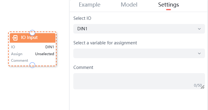
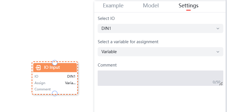
Program Example: In the program segment, set up to read the input level of DIN1 and assign it to the variable test, as shown in the figure below:
IO Mode
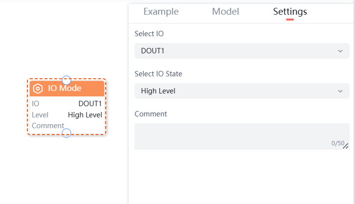
The "IO Mode" command is used to set the output level (high or low) of the controller IO (DOUT1, DOUT2, DOUT3, DOUT4) or the end-effector IO (T_DOUT1, T_DOUT2).
This can be used to set the output level of the controller IO (DOUT1, DOUT2, DOUT3, DOUT4) or the end-effector IO (T_DOUT1, T_DOUT2).
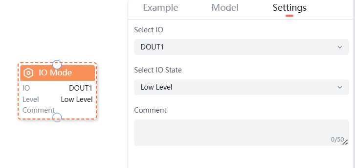
Program Example: In the program segment, set the output level of DOUT1 to high, as shown in the figure below:
Modbus Command
The Modbus command includes two commands: "Read" and "Write".
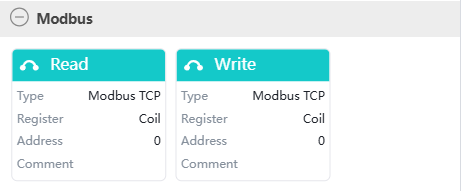
Read
The "Read" command is divided into three types: "Modbus TCP", "Modbus RTU", and "Robot Slave".
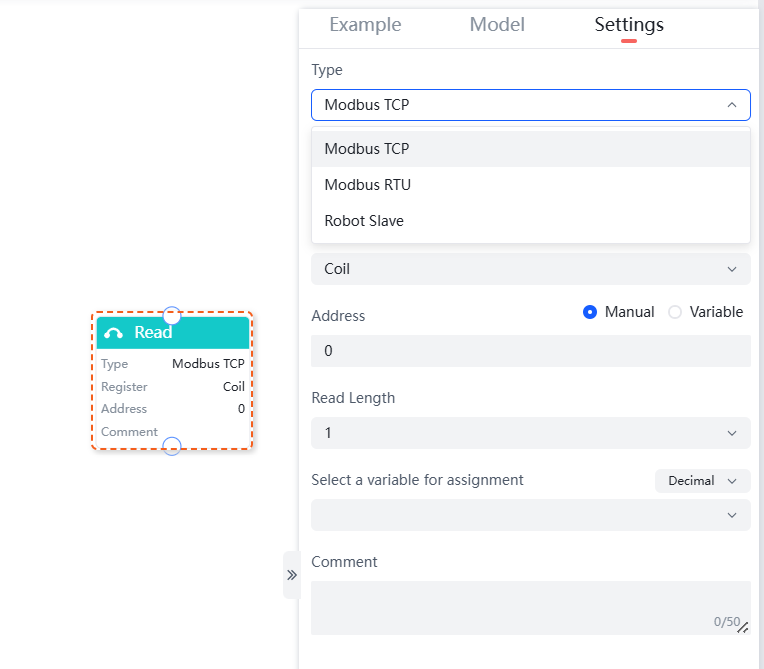
Different types of "Read" commands support the following parameter settings:
- Modbus TCP: Supports selecting a device, register, and setting the address, read length, and variable for assignment.
- Modbus RTU: Supports selecting a device, register, and setting the peripheral device address, address, read length, and variable for assignment.
- Robot Slave: Supports selecting a register type and setting the address, read length, and variable for assignment.
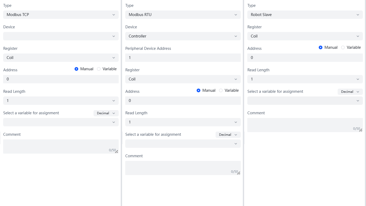
- Type: Choose the type of read command based on your needs, supporting Modbus TCP, Modbus RTU, and Robot Slave.
- Device: The available devices are automatically adapted based on the selected type.
- Peripheral Device Address: Enter the peripheral device address.
- Register: Select the register type, supporting Coil, Discrete Input, Holding Register, and Input Register.
- Address: Set the read address, which can be done manually or by selecting a manually added variable.
- Read Length: Select the length of data to read; currently, only setting it to 1 is supported.
- Select a Variable for Assignment: Choose the target variable for assignment, supporting decimal, signed decimal, and hexadecimal.
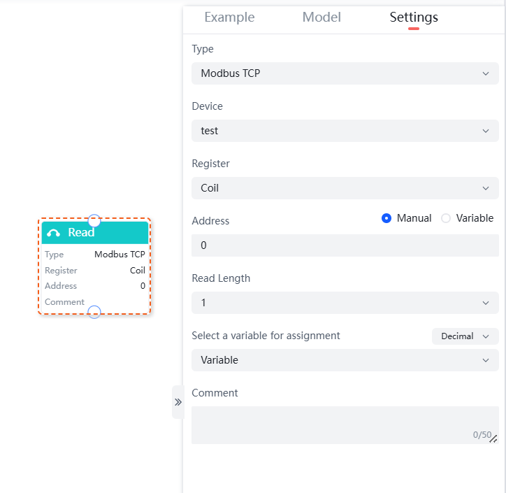
Program Example: Add a read command of type Modbus TCP in the program segment as shown in the figure below.
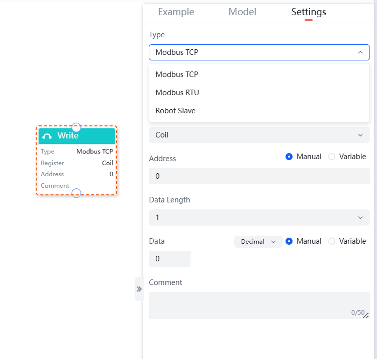
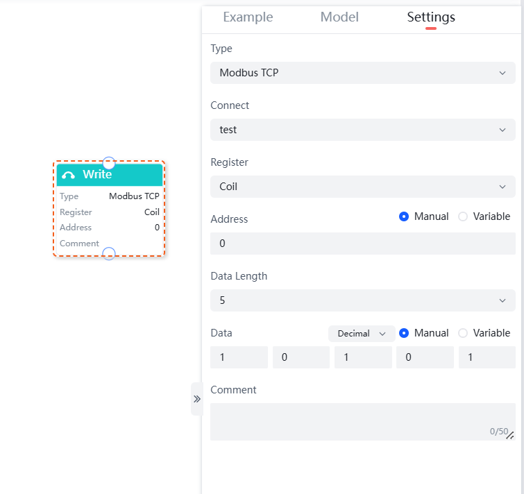
Write
The "Write" command is divided into three types: "Modbus TCP", "Modbus RTU", and "Robot Slave".
Different types of "Write" commands support the following parameter settings:
- Modbus TCP: Supports selecting a device, register, and setting the address, data length, and data.
- Modbus RTU: Supports selecting a device, register, and setting the peripheral device address, address, data length, and data.
- Robot Slave: Supports selecting a register and setting the address, data length, and data.
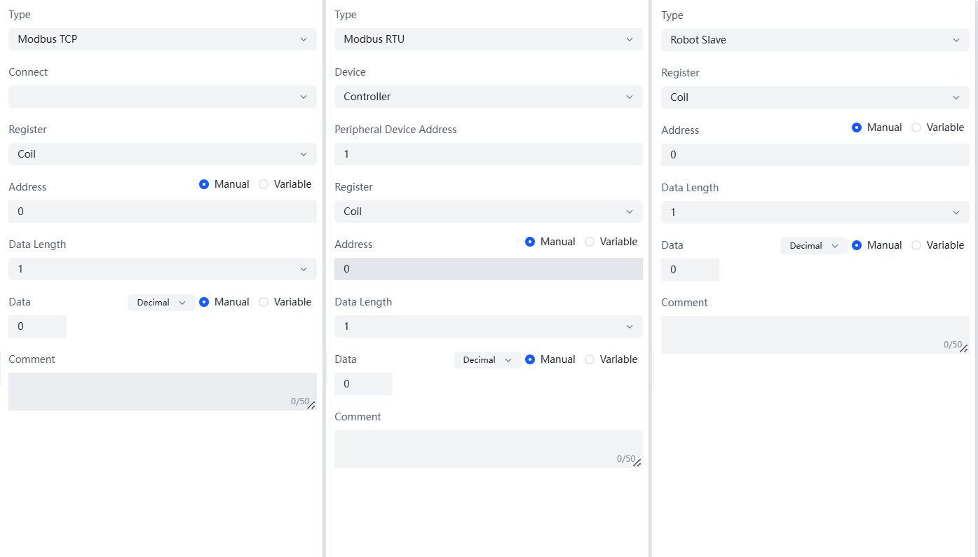
- Type: Choose the type of write command as needed, supporting Modbus TCP, Modbus RTU, and Robot Arm Slave.
- Connect: Automatically adapts to available connects based on the selected type.
- Device: Automatically adapts to available devices based on the selected type.
- Peripheral Device Address: Enter the peripheral device address.
- Register: Select the register type, supporting Coil, Discrete Input, Holding Register, and Input Register.
- Address: Set the write address, which can be done manually or by selecting a manually added variable.
- Data Length: Choose the length of the data to be written, supporting 1~10.
- Data: Enter the data to be written, which only supports 0 or 1. Depending on the data length, different lengths of data need to be entered; when entering manually, it supports setting to decimal, signed decimal, and hexadecimal; it also supports setting by selecting a manually added variable.
Program Example: Add a write command of type Modbus TCP in the program segment, as shown in the following figure.
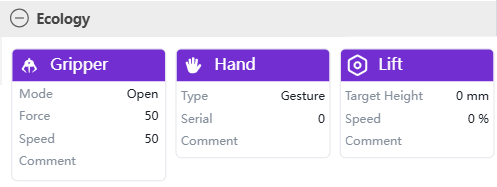
Ecology Commands
Eco commands include "Gripper," "Hand," and "Lift" commands.
Gripper
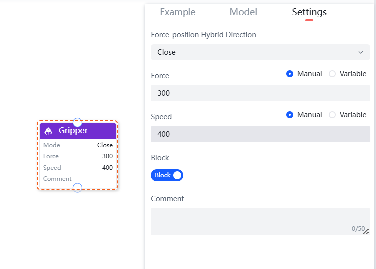
The "Gripper" command is used to control the two-finger gripper. It can control the force-position hybrid direction, force, speed, and block.
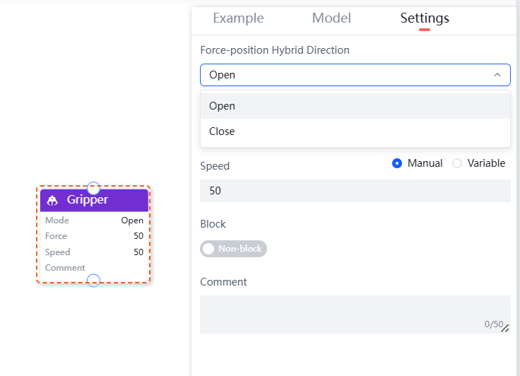
Force-Position Hybrid Direction: The gripping action includes two force-position hybrid directions: open and close.
Force: Set the gripping force, with a settable range of 50-1000.
Speed: Set the gripper's operating speed, with a settable range of 1-1000.
Block: Divided into blocking and non-blocking modes. In blocking mode, the robot executes subsequent commands after the gripper movement is completed; in non-blocking mode, the robot executes subsequent programs while the gripper is moving.
Program Example: Add a gripper command in the program segment:
Gripper Open as Shown Below: The gripper blocking mode is enabled, speed: 400, force: 300.
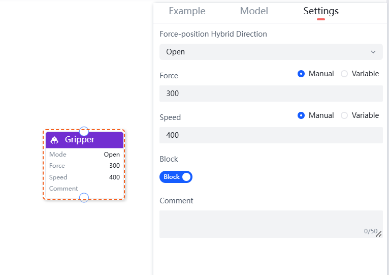
Gripper Close as Shown Below: The gripper blocking mode is enabled, speed: 400, force: 300.
Hand
The "Hand" command is used to control the five-finger dexterous hand. It can set the type, gesture, action sequence, and block.
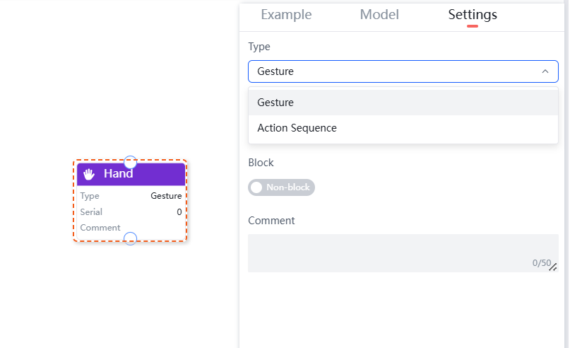
Gesture: Pre-stored gestures of the dexterous hand, which can be set manually or by selecting a manually added variable.
Action Sequence: Pre-stored gesture numbers of the dexterous hand, settable from 1-40. Each number represents one gesture action, which can be set manually or by selecting a manually added variable.
Block: Divided into blocking and non-blocking modes. In blocking mode, the robot executes subsequent commands after the dexterous hand movement is completed; in non-blocking mode, the robot executes subsequent programs while the dexterous hand is moving.
Program Example: Add a dexterous hand command in the program segment, as shown in the following figure:
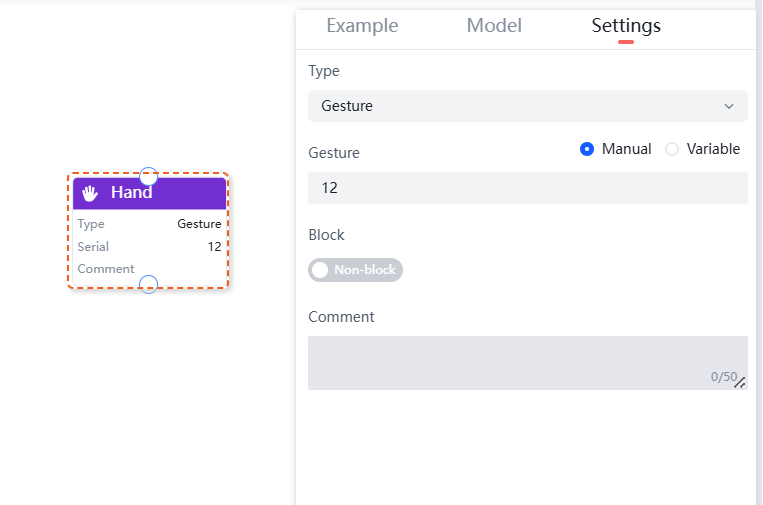
In the program, the gesture of the dexterous hand command is: 12.
Lift
The "Lift" command is used to control the movement of the robot's extended joint lift or slide table. It can set the target height, speed, and block.
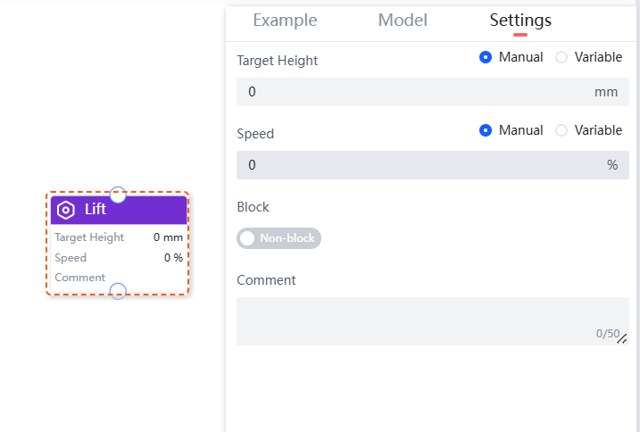
Target Height: Position control of the lift mechanism. Set the position based on the actual working position of the robot, noting the actual travel of the lift mechanism. The parameter setting range is 0-3000mm.
Speed: Set the movement speed of the lift mechanism. The default speed is 0%. The parameter setting range is 0-100.
Block: Divided into blocking and non-blocking modes. In blocking mode, the robot executes subsequent commands after the lift mechanism reaches its target position; in non-blocking mode, the robot executes subsequent programs while the lift mechanism is moving.
Program Example: Add a lift trajectory in the program segment, as shown in the following figure.
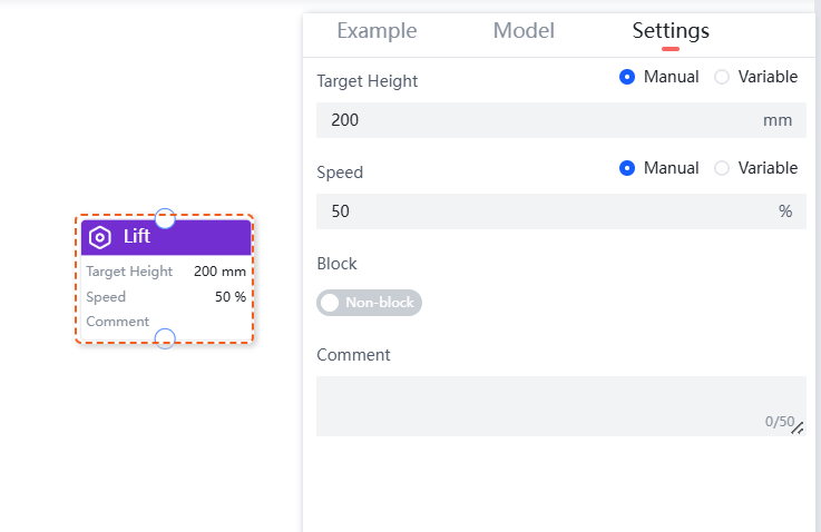
In the lift command in the program, the target height is: 200mm, and the speed is: 50%.
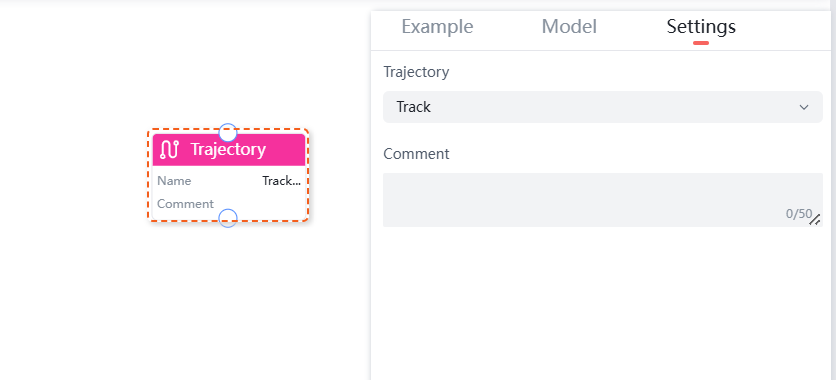
Trajectory Command
The trajectory command includes one Command: "Trajectory."
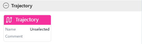
Trajectory
The "Trajectory" command is used to set the robotic arm to move according to a saved trajectory file.
Force Control Command
Force control Command include two commands: "Force Control" and "Force Stop."
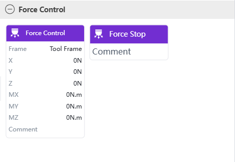
Force Control
The Force Control command is applicable only to robots equipped with a six-axis force sensor at the end-effector. The parameters to be set include selecting the coordinate system and force-position hybrid control.
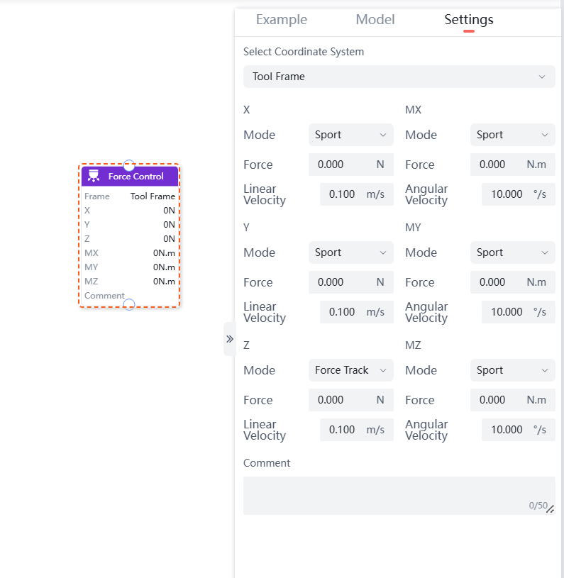
Select Coordinate System: Choose the reference coordinate system for force control.
Force-Position Hybrid Control: The six-axis force sensor can select one or multiple directions from X\Y\Z\Rx\Ry\Rz, and set the mode, force, and linear/angular velocity for force-position hybrid control.
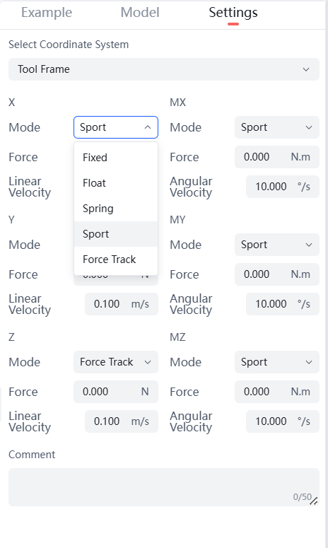
- Available modes for X\Y\Z\Rx\Ry\Rz include: Fixed, Float, Spring, Sport, Force Track.
- Force range for X\Y\Z directions: -100~100N.
- Linear velocity range for X\Y\Z directions: 0~0.200m/s, default is 0.100m/s.
- Force range for Rx\Ry\Rz directions: -7.000~7.000N·m.
- Angular velocity range for Rx\Ry\Rz directions: 0~10.000°/s, default is 10.000°/s.
WARNING
- Points moved by force-position hybrid control must be recorded in Cartesian coordinates, i.e., MOVEJ commands are not allowed.
- The point preceding the force control must be consistent with the first point of the force control.
- When starting the force control command, do not apply external forces to the force sensor to avoid affecting calibration (refer to the programming example).
Program Example: Add a force control command in the program segment, where the linear motion in the loop is the force control process, as shown in the figure below.

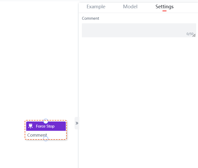
Force Stop
The Force Stop command is used to terminate the force control process.
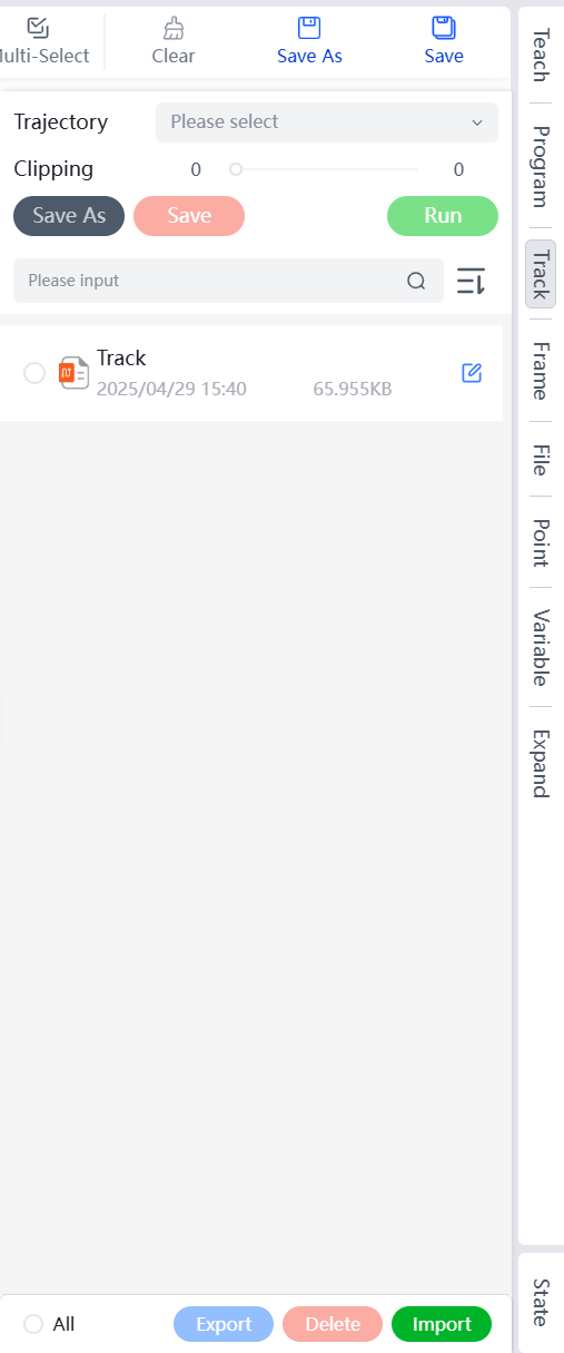
Track Menu
The track management page displays the trajectory name, file size, and creation time. It supports operations such as Edit, Export, Delete, Import, and Clipping. Sorting can be done based on Chronological, Reverse Chronological, Reversed names, Ordered names, Reversed Size, and Ordered Size.
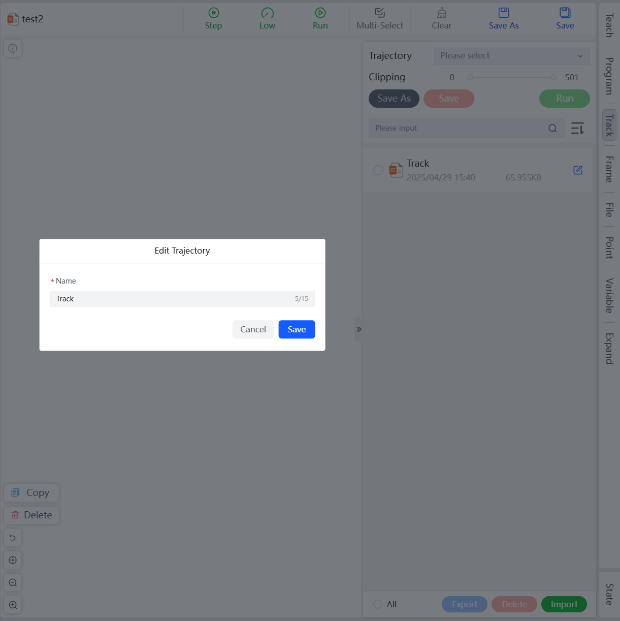
Edit
Modify the name of the saved trajectory.
Click the edit button to the right of the target trajectory to open the edit trajectory dialog box. Enter the new file name and click Save to complete the name editing.
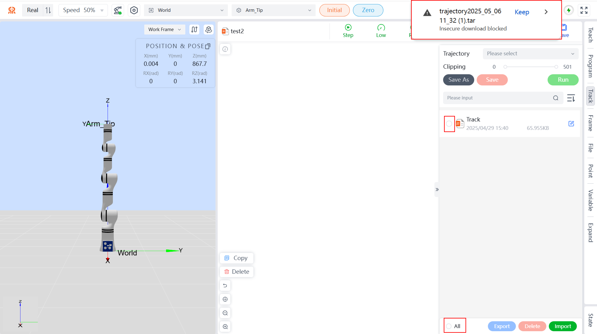
Export
Export the trajectory file to your local machine.
Select the trajectory file you want to export. You can click All at the bottom left to choose all trajectory files, then click the Export button to export the trajectory files to the download path set in your browser, with a .tar extension.
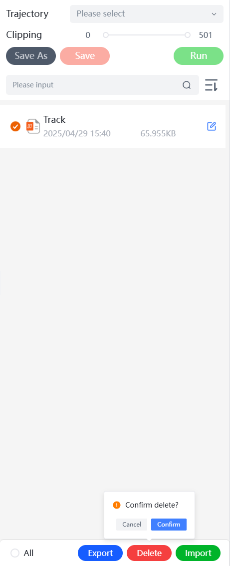
Delete
Delete the trajectory file.
Select the trajectory file you want to delete. You can click All at the bottom left to choose all trajectory files, then click the Delete button. In the pop-up confirmation box, click Confirm to delete the selected trajectory file.
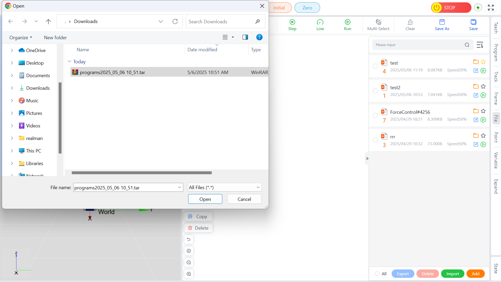
Import
Import a trajectory file from your local machine.
Click the Import button and select the target trajectory file in the pop-up dialog box. Click Open to complete the import of the trajectory file.
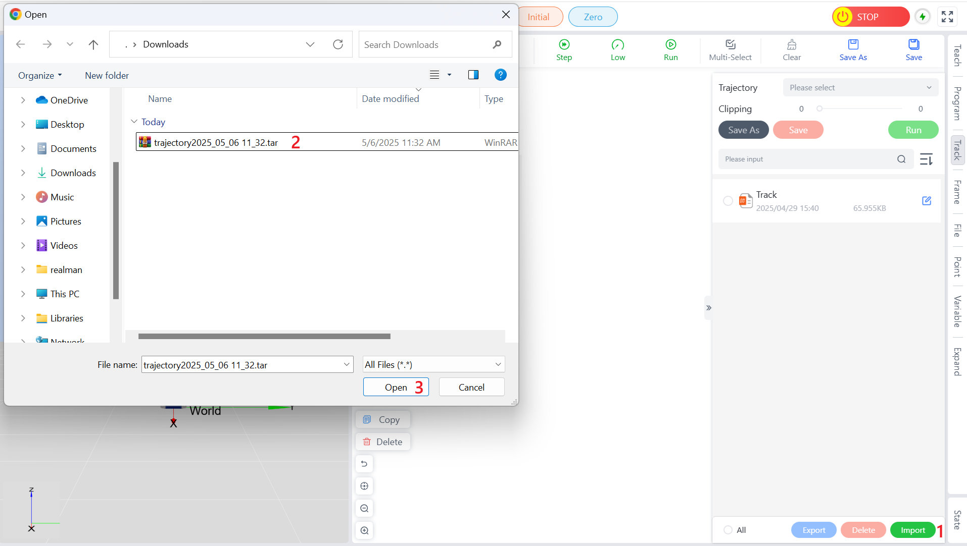
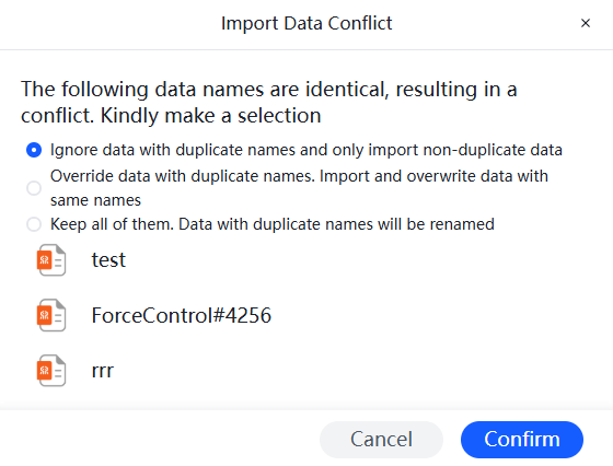
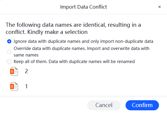
Note: If the imported trajectory file conflicts with a trajectory file already in the teaching device, a prompt will appear. Choose the appropriate handling method and click Confirm to complete the import.

Clipping
By dragging the saved teaching trajectory, you can choose to run or Clipping it here. Click the dropdown box to select the trajectory you want to run, then click the Run button to start the trajectory. You can click the Stop button at any time during the run to stop it, and it will stop automatically after completion.
Drag the sliders at both ends of the progress bar to Clipping the trajectory. As shown in the figure below, when dragging the sliders, a red virtual robotic arm will display the pose of each point in the trajectory in real-time, helping users determine the Clipping points. After Clipping, click the Save button to overwrite the original trajectory with the Clipped one, or click the Save As button to save the Clipped trajectory as a new file.
- Save: Overwrite the previous trajectory file with the Clipped trajectory.
- Save As: Save the Clipped trajectory as a new file, requiring a new file name.
Button Table
| Dropdown Box | Run Trajectory | Stop Trajectory | Save | Save As |
|---|---|---|---|---|
 |  |  |  |  |
Frame Menu
Work Frame
The work Frame calibration is shown in the figure below, displaying the names of all current work Frames and their poses relative to the base Frame.
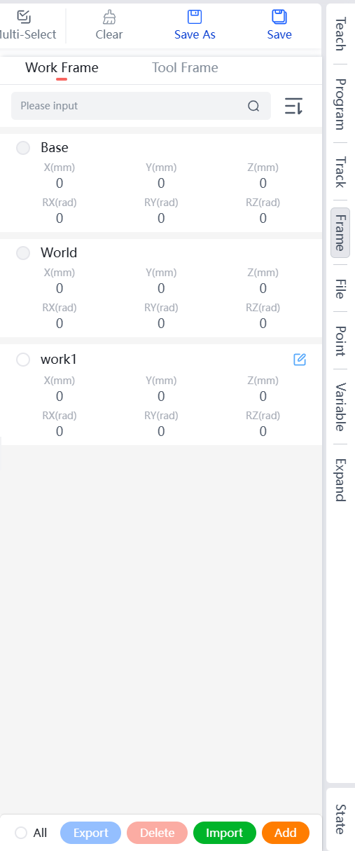
List of Work Frames
Displays the names and pose parameters of all work Frames that have been established for the current robot.
- Supports sorting in ascending or descending order by name.
- Allows for precise search by Frame name, note that letters are case-sensitive.
Adding a Work Frame
Work Frames can be added in two ways: manual calibration and auto calibration. Please refer to the corresponding descriptions based on your needs.
Manually Setting a Work Frame
When the user knows the exact relative pose of the Frame with respect to the robot's base Frame, they can set the work Frame by manually entering the information.
- On the work Frame page, click the
Addbutton below the Frame list. - Input the pose information of the new Frame on the manual calibration tab, click the
Addbutton at the bottom right of the page. - In the pop-up "New Frame" dialog box, enter the name of the work Frame (English characters, no more than 10 characters), click
Add, and then send the new Frame information to the robot controller, which will be displayed in the Frame table.
Auto Calibration a Work Frame
On the work Frame page, click the Add button below the Frame list, then calibrate the current work Frame using the three-point method on the auto calibration tab. Position the robot tool end in a fixed posture to touch three points of the work Frame: the origin, any point on the positive X-axis (as far as possible more than 10cm from the origin), and any point on the positive Y-axis (as far as possible more than 10cm from the origin).
| No. | Name |
|---|---|
| 1 | Position the robot tool end in a fixed posture to touch the origin of the work Frame 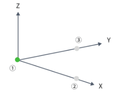 |
| 2 | Touch any point on the positive X-axis of the work Frame, as far as possible more than 10cm from the origin 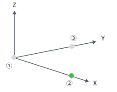 |
| 3 | Touch any point on the positive Y-axis of the work Frame, as far as possible more than 10cm from the origin 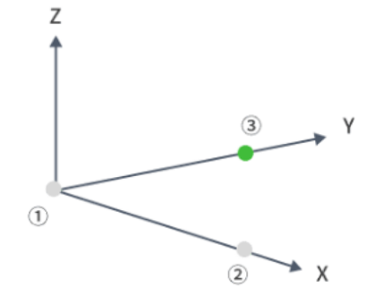 |
After calibrating these three points, click the Add button at the bottom right of the page, and in the pop-up "New Frame" dialog box, enter the name of the work Frame (English characters, no more than 10 characters). The system will automatically calculate the information of the current Frame based on these three calibration points, and after calculation, it will send the information back to the teaching pendant and display it in the Frame table. After calibration, the robot will enter the base Frame for operation.
Editing a Work Frame
The system supports editing manually added work Frame information.
Click the edit button to the right of the target Frame to enter the work Frame calibration page.
Follow the steps in Adding a Work Frame to complete the update of the work Frame calibration information.
Export a Work Frame
The system supports exporting manually added work Frame information.
Select the target Frame to be exported; you can select all manually added work Frames by clicking
Allat the bottom.Click
Exportat the bottom of the list, and the system will automatically download the corresponding Frame information to your browser's download directory in .TXT format.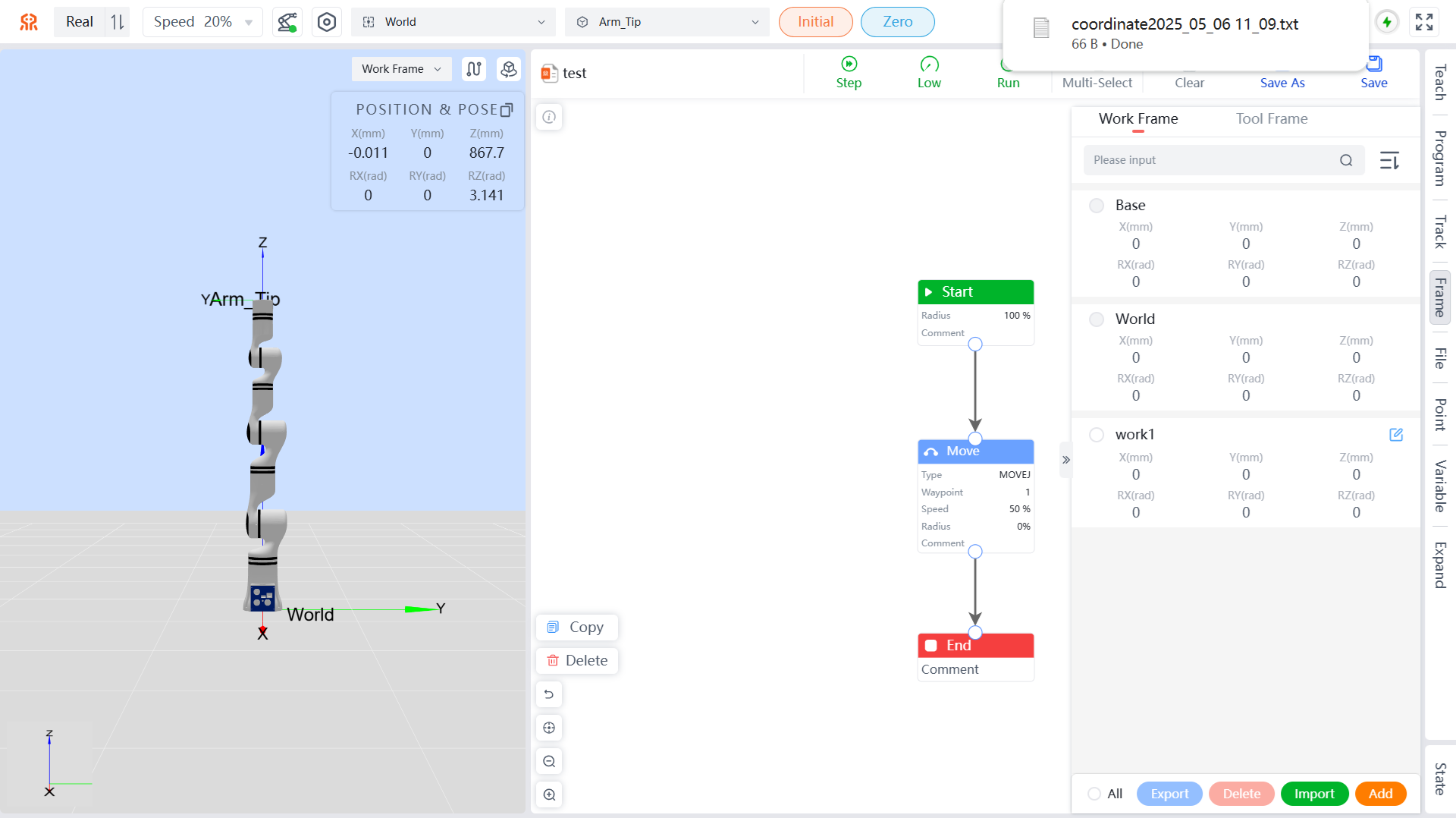
Delete a Work Frame
The system supports deleting manually added work Frame information.
Select the target Frame to be deleted; you can select all manually added work Frames by clicking
Allat the bottom.Click
Deleteat the bottom of the list, and in the pop-up dialog box, clickConfirmto complete the deletion of the target work Frame.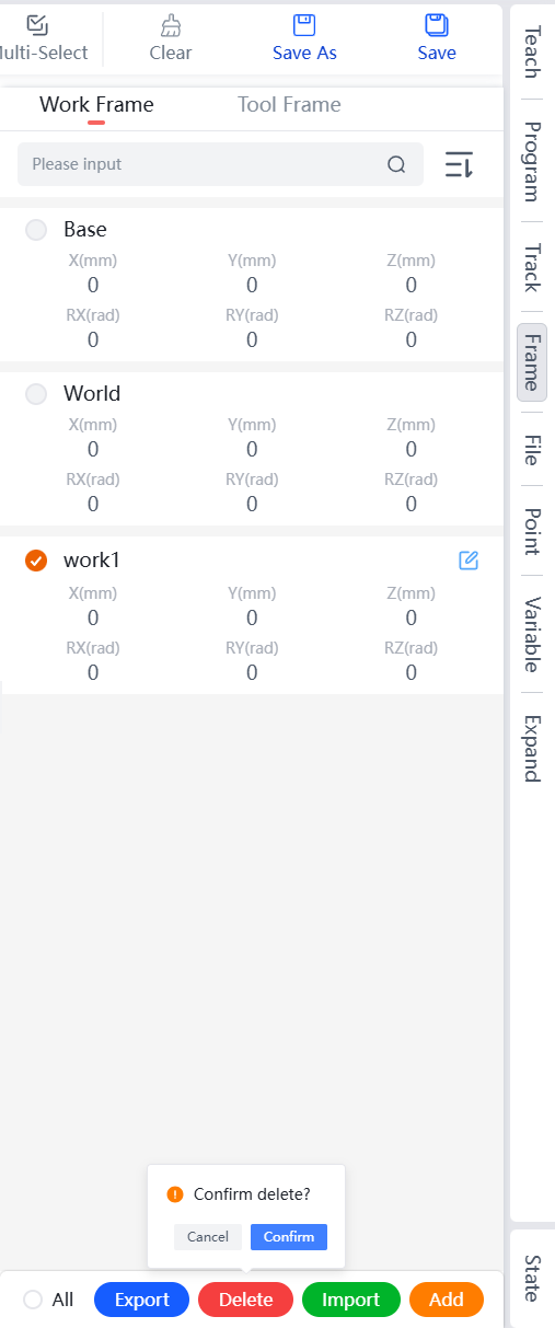
Import a Work Frame
The system supports importing work Frame information.
Click
Importat the bottom of the list, and in the pop-up dialog box, select the corresponding work Frame file.Click
Opento complete the import of the work Frame. If the imported work Frame has a name conflict with an existing one in the system, a dialog box will appear as shown below. Please choose the appropriate import method based on your needs and clickConfirmto complete the import.
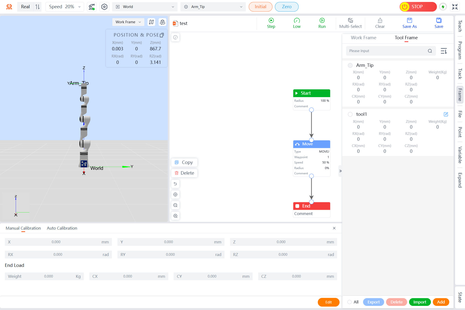
Tool Frame
The tool Frame calibration is shown in the figure below, displaying all current tool Frames and tool pose information.
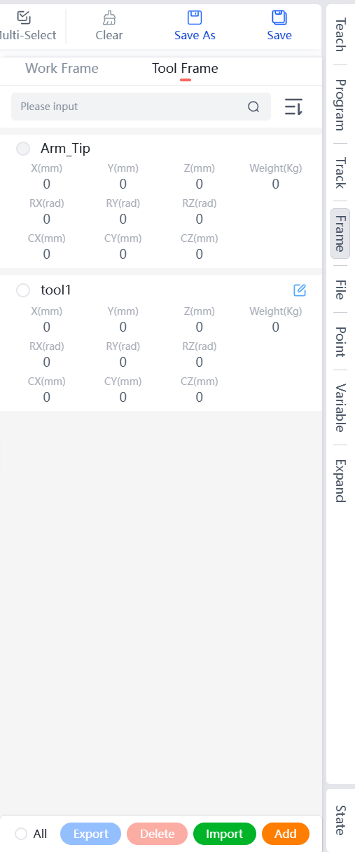
List of Tool Frames
Displays the names and pose parameters of all tool Frames that have been established for the current robot.
- Supports sorting in ascending or descending order by name.
- Allows for precise search by Frame name, note that letters are case-sensitive.
Adding a Tool Frame
Tool Frames can be added in two ways: manual calibration and auto calibration. Please refer to the corresponding descriptions based on your needs.
Manually Setting a Tool Frame
When the user knows the exact relative pose of the tool with respect to the robot's end-effector flange center, they can set the tool Frame by manually entering the information.
- On the tool Frame page, click
Addbelow the Frame list. - Input the new pose and end load information on the manual calibration tab, click
Addat the bottom right of the page. - In the pop-up "New Frame" dialog box, enter the tool name (English characters, no more than 10 characters), click
Add, and then send the new tool information to the robot controller, which will be displayed in the tool table.
After successful calibration, the robot will enter the end-effector flange center tool Frame for operation.
Auto Calibration a Tool Frame
On the tool Frame page, click
Addbelow the Frame list.Calibrate the current tool Frame using the six-point method on the automatic calibration tab. Position the robot tool in six different postures to touch a reference point (the reference point should be sharp and placed vertically within the robot's working range).
The rules for 6-point calibration are as follows:
No. Name 1 ny posture, the tool tip contacts the reference tip 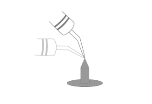
2 Any posture, the tool tip contacts the reference tip 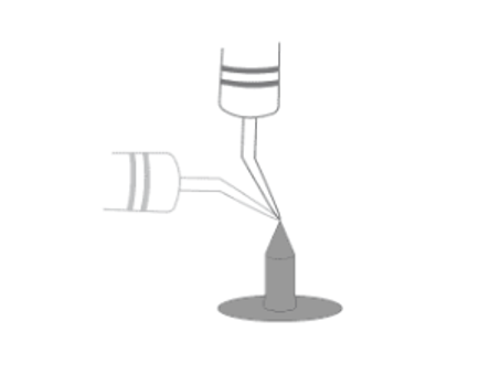
3 Any posture, the tool tip contacts the reference tip 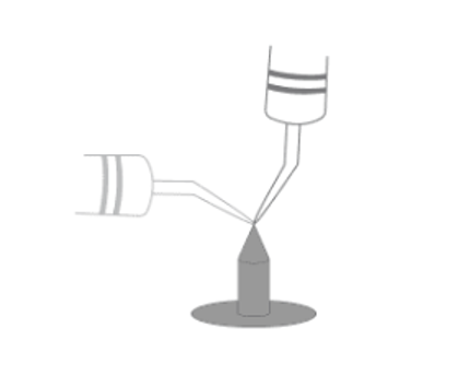
4 The tool tip is vertically downward and contacts the reference tip 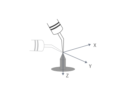
5 Maintain the posture of point 4, move from point 4 along the positive direction of the X-axis of the tool Frame to point 5, the distance between this position and point 4 should be as large as possible, greater than 10cm 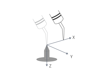
6 Maintain the posture of point 4, move from point 4 along the negative direction of the Z-axis of the tool Frame to point 6, the distance between this position and point 4 should be as large as possible, greater than 10cm 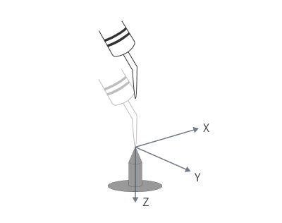
WARNING
The postures of the first 4 points should be as different as possible; do not select the same points.
After completing the calibration of 6 points, click the
Addbutton at the bottom right of the page, and in the pop-up "New Frame" dialog box, enter the tool name (English characters, no more than 10 characters).Click
Add. The system will start to automatically calculate the current tool information based on the 6 calibration points. After the calculation is completed, it will be transmitted back to the teaching pendant and displayed in the tool table.
Edit Tool Frame
The system supports editing manually added tool Frame information.
Click the edit button on the right side of the target Frame to enter the tool Frame calibration page.
Refer to Adding a Tool Frame to complete the update of the tool Frame calibration information.
Export Tool Frame
The system supports exporting manually added tool Frame information.
Select the target Frame to be exported; you can select all manually added tool Frames by clicking
Allat the bottom.Click
Exportat the bottom of the list, and the system will automatically download the corresponding Frame information to the browser's download directory in .TXT format.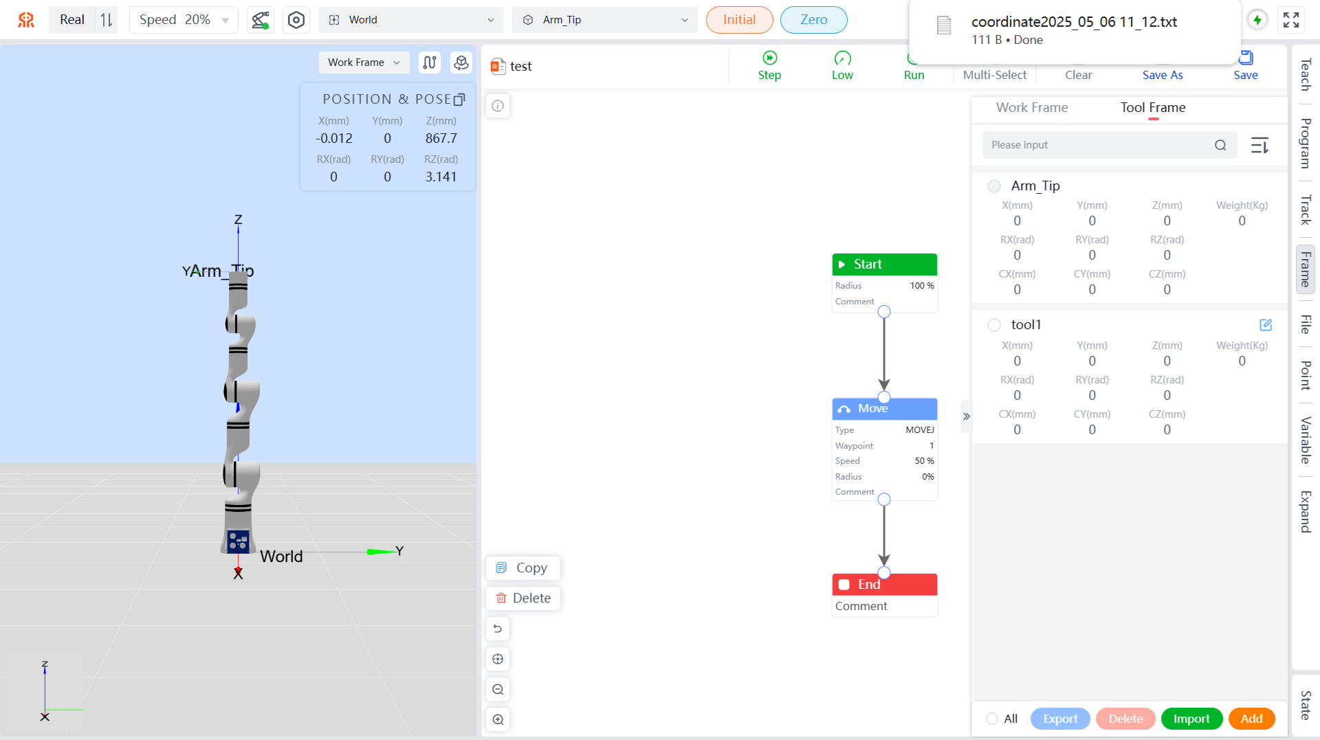
Delete Tool Frame
The system supports deleting manually added tool Frame information.
Select the target Frame to be deleted; you can select all manually added tool Frames by clicking
Allat the bottom.Click
Deleteat the bottom of the list, and in the pop-up dialog box, clickConfirmto complete the deletion of the target tool Frame.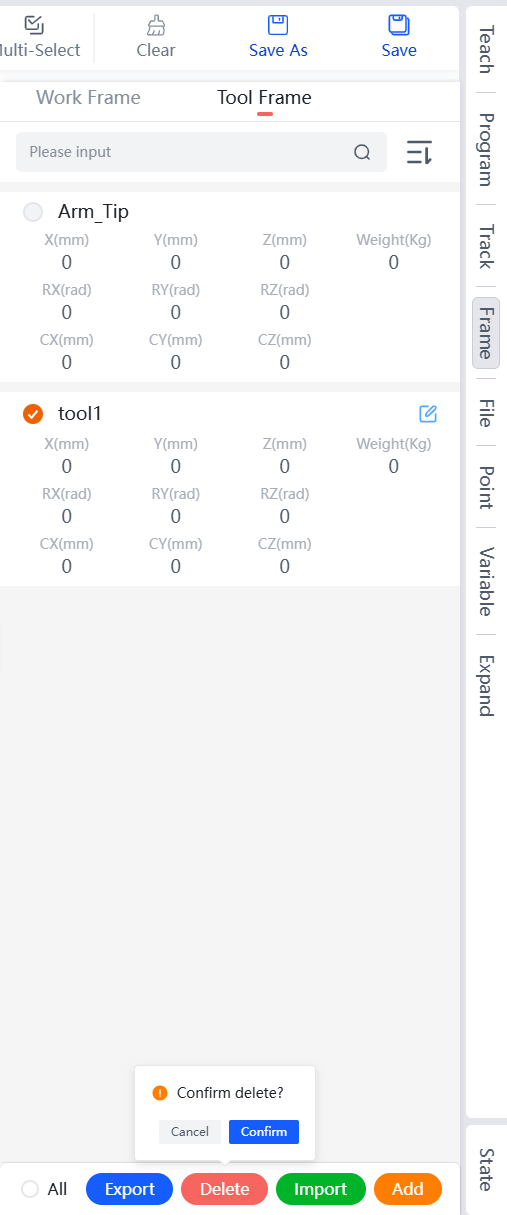
Import Tool Frame
The system supports importing tool Frame information.
Click
Importat the bottom of the list, and in the pop-up dialog box, select the corresponding tool Frame file.Click
Opento complete the import of the tool Frame. If the imported tool Frame has a name conflict with an already added Frame, a dialog box will pop up. Please choose the corresponding import method according to your needs and clickConfirmto complete the import.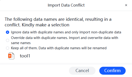
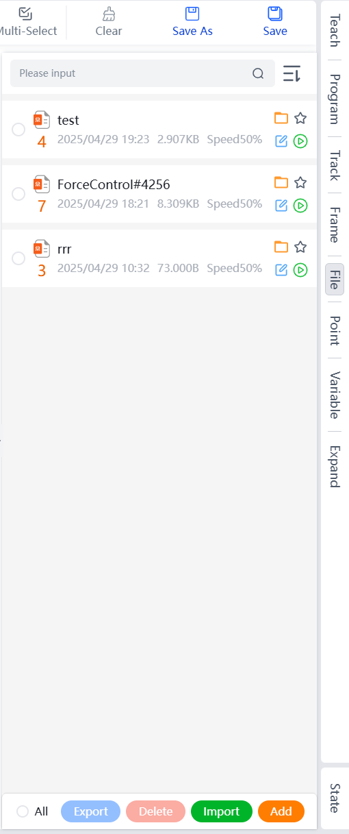
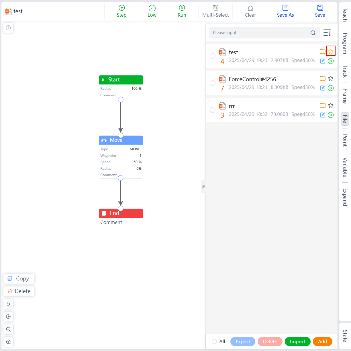
File Menu
The file management page displays programming file names, numbers, file sizes, last edit times, and speeds, and supports operations such as Open, Set as Default, Edit, Run, Export, Delete, Import, and Add.
- Supports sorting by Chronological, Reverse Chronological, Reversed names, Ordered names, Reversed Size, and Ordered Size.
Open
Supports opening saved programming files from the file list.
In the file list, click the open button on the right side of the target programming file to complete the opening operation of the corresponding programming file.

Set as Default
The system supports setting a programming file as the default programming file. In this case, when entering the teaching pendant subsequently, the default programming file will be opened automatically.
In the file list, click the set as default button on the right side of the target programming file to complete setting it as default.
Edit
Modify the name, number, and speed of saved programming files.
In the file list, click the edit button on the right side of the target programming file.
In the pop-up edit file dialog box, enter the modified file name, number, and speed, and then click
Saveto complete editing of the programming file.
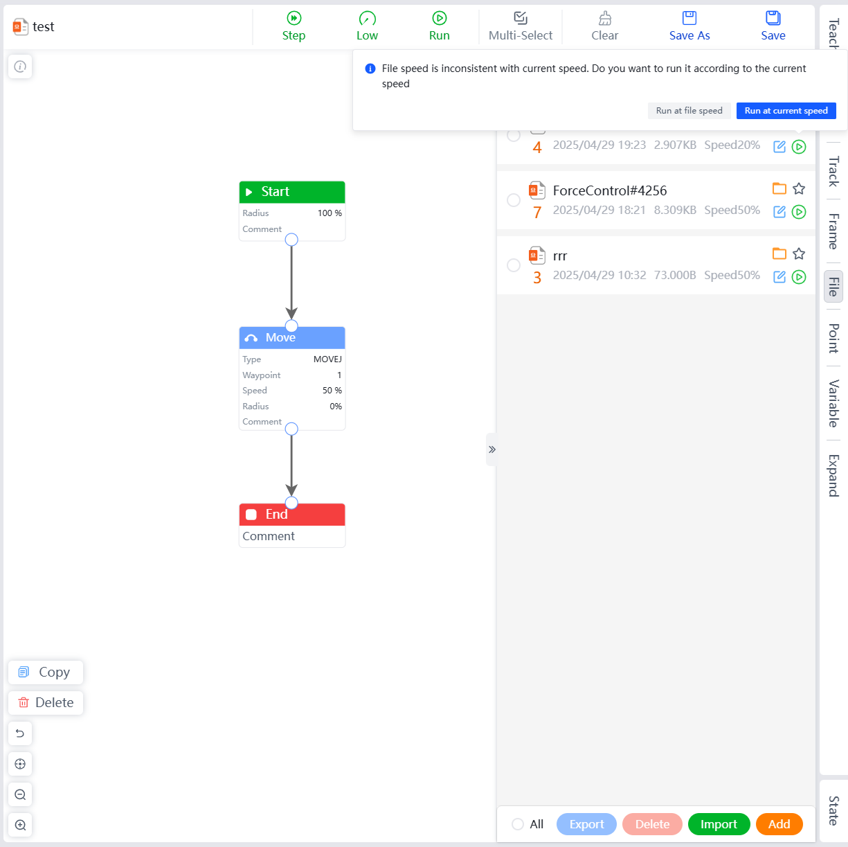
Run
Supports running saved programming files directly in the programming file list.
In the file list, click the run button to the right of the target programming file, which will open the corresponding programming file and run it directly.

If the speed setting of the programming file is inconsistent with the current running speed, a prompt will appear indicating the speed inconsistency. Please choose to run at the file's speed or the current speed as needed.
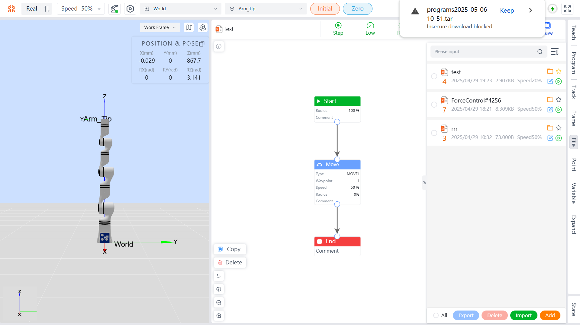
Export
Programming files can be exported to your local system.
Select the programming files you wish to export. You can select all programming files by clicking the All button at the bottom left, then click the Export button to export the programming files to the download path set in your browser, with a .tar extension.
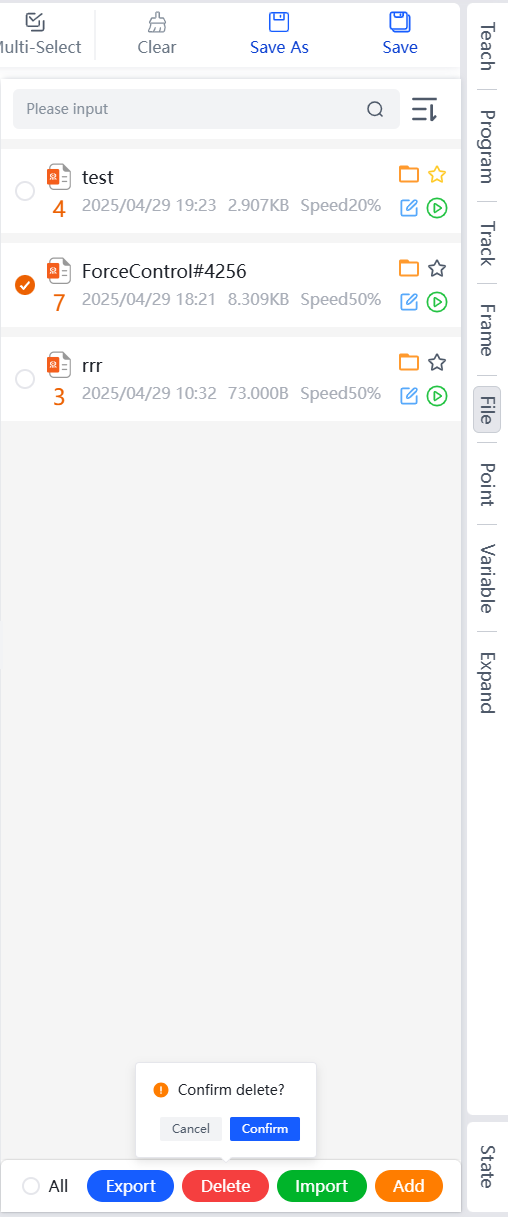
Delete
When a programming file is no longer needed, you can delete it.
Select the programming files you wish to delete. You can select all programming files by clicking the All button at the bottom left, then click the Delete button. In the confirmation dialog that appears, click Confirm to delete the selected programming files.
Import
Supports importing programming files from your local system.
Click the Import button, and in the dialog that appears, select the target programming file and click Open to complete the import.
Note: If the imported programming file conflicts with an existing file in the programmer, a prompt will appear. Please choose the appropriate handling method and click Confirm to complete the import.
Add
Used to create new programming files.
Click the
Addbutton, and in the dialog that appears, set the file name, number, and speed.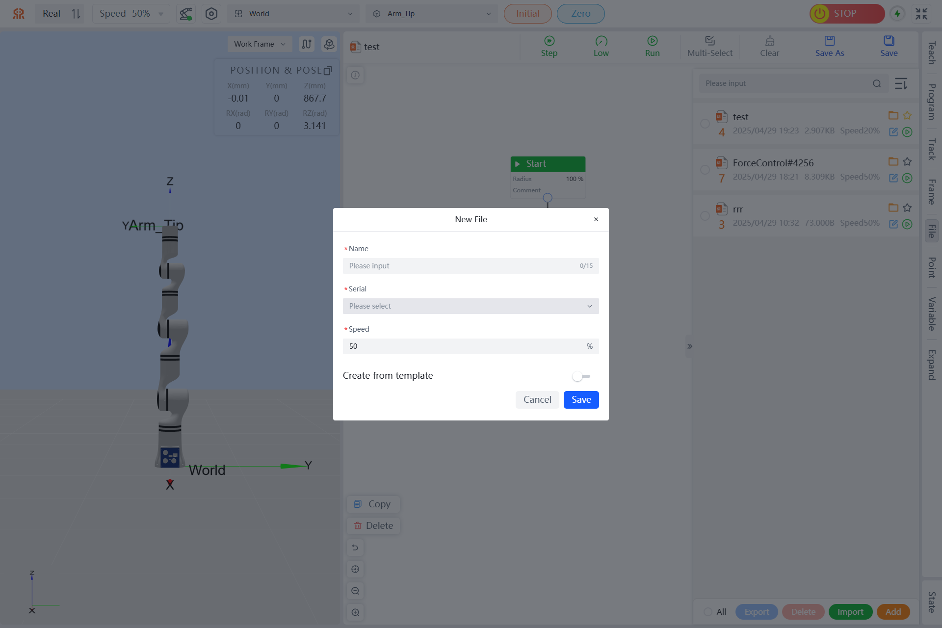
(Optional) The programmer supports creating new files from templates. Click the switch to the right of "Select from Template" to display available templates, and choose the appropriate template as needed.
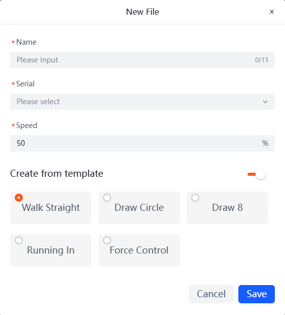
Click
Saveto complete the creation of the new programming file.
The new programming file will be automatically added to the file list.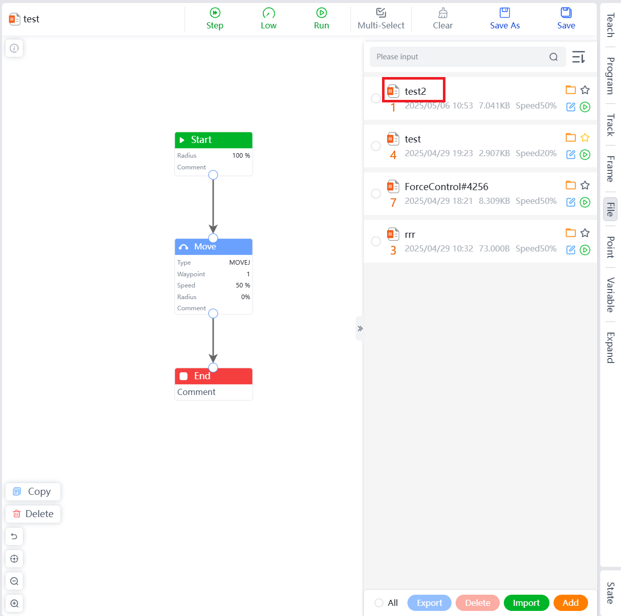
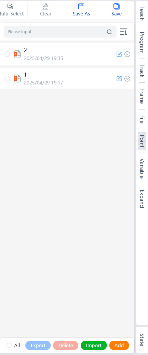
Point Menu
The point management page displays point names and creation times, and supports operations such as Edit, View Detailed Parameters, Export, Delete, Import, and Add.
- Supports sorting by Chronological, Reverse Chronological, Reversed names, Ordered names.
- Supports precise search by file name or number.
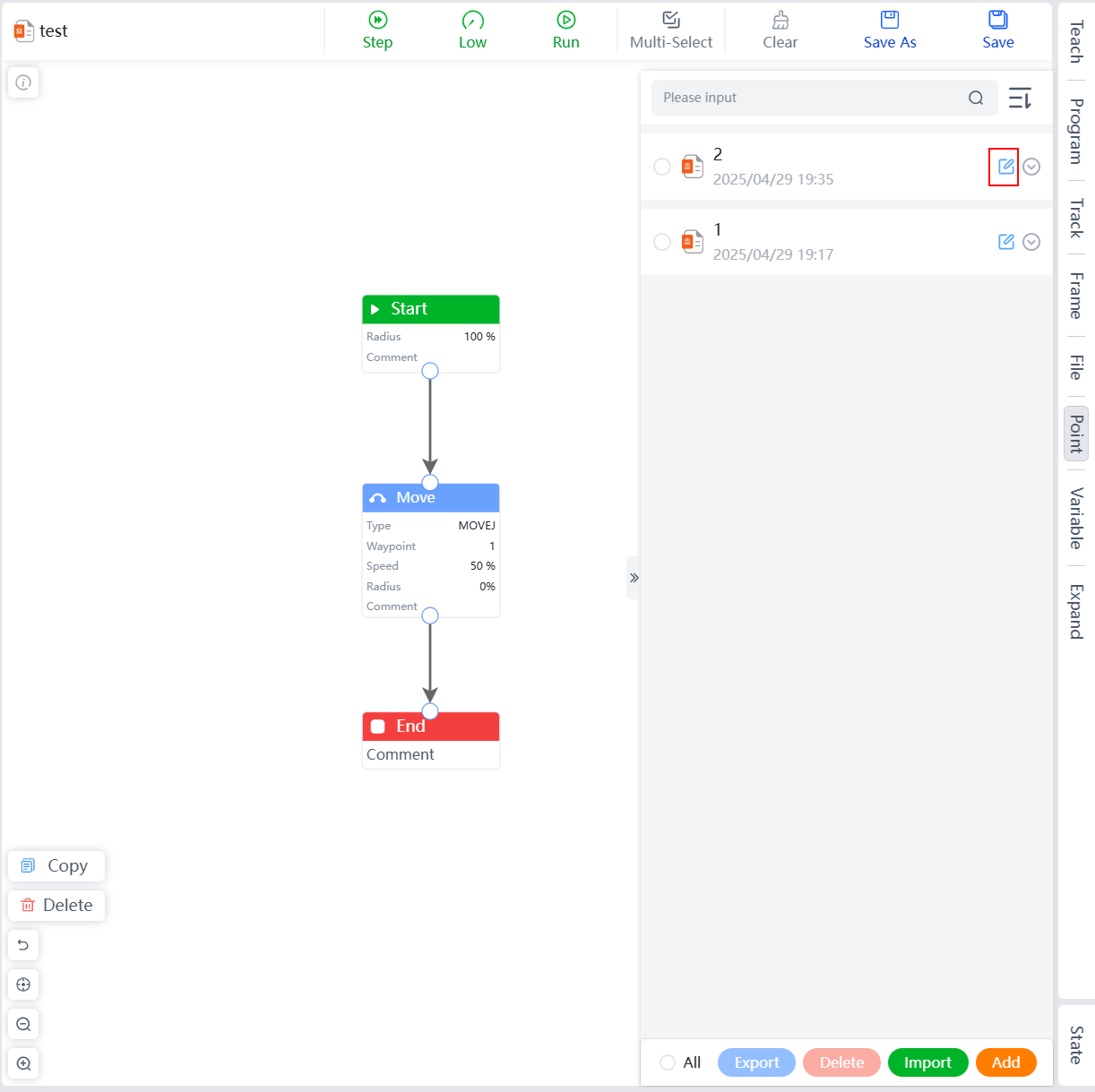
Edit
Modify saved point parameters, names, and notes.
In the point list, click the edit button to the right of the target point to navigate to the teaching menu.
Modify the corresponding parameters in the teaching or editing tab as needed, and click
Editbelow.
In the edit point dialog that appears, enter the modified point name and notes, then click
Saveto complete the editing of the point.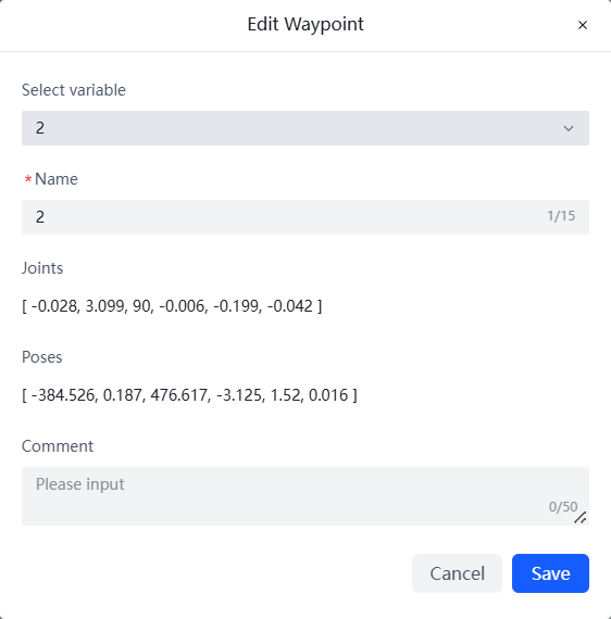
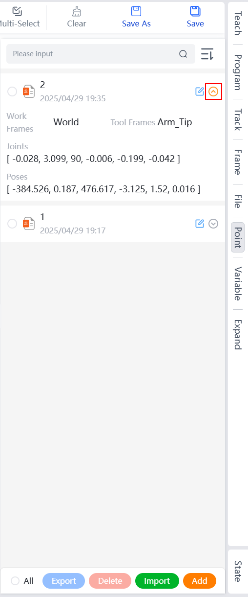
View Detailed Parameters
The point list supports viewing detailed parameters of points.
In the point list, click the expand button to the right of the target point to display detailed information about the point, including the working coordinate system, tool coordinate system, and joint and pose information.
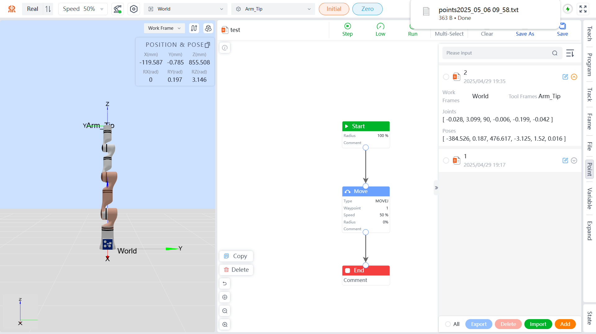
Export
Point files can be exported to the local system.
Select the point files to be exported. You can select all point files by clicking the All button at the bottom left, then click the Export button to export the point files to the download path set in your browser, with the file extension .TXT.
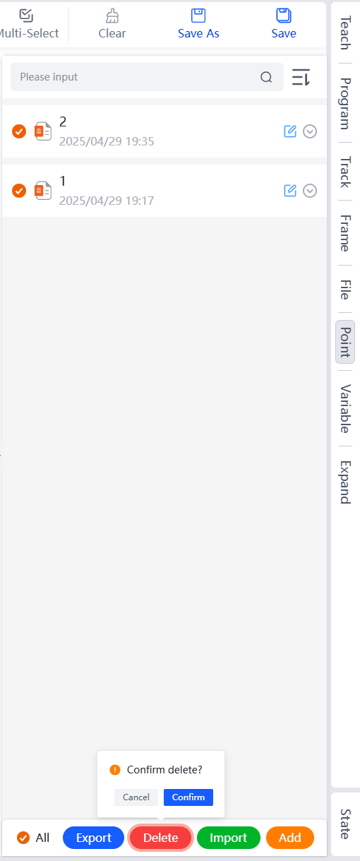
Delete
When point files are no longer needed, you can delete the corresponding point files.
Select the point files to be deleted. You can select all point files by clicking the All button at the bottom left, then click the Delete button. In the pop-up confirmation box, click Confirm to complete the deletion of the target point files.
Import
You can import point files from your local system.
Click the Import button, and in the pop-up dialog box, select the target point file, then click Open to complete the import of the point file.
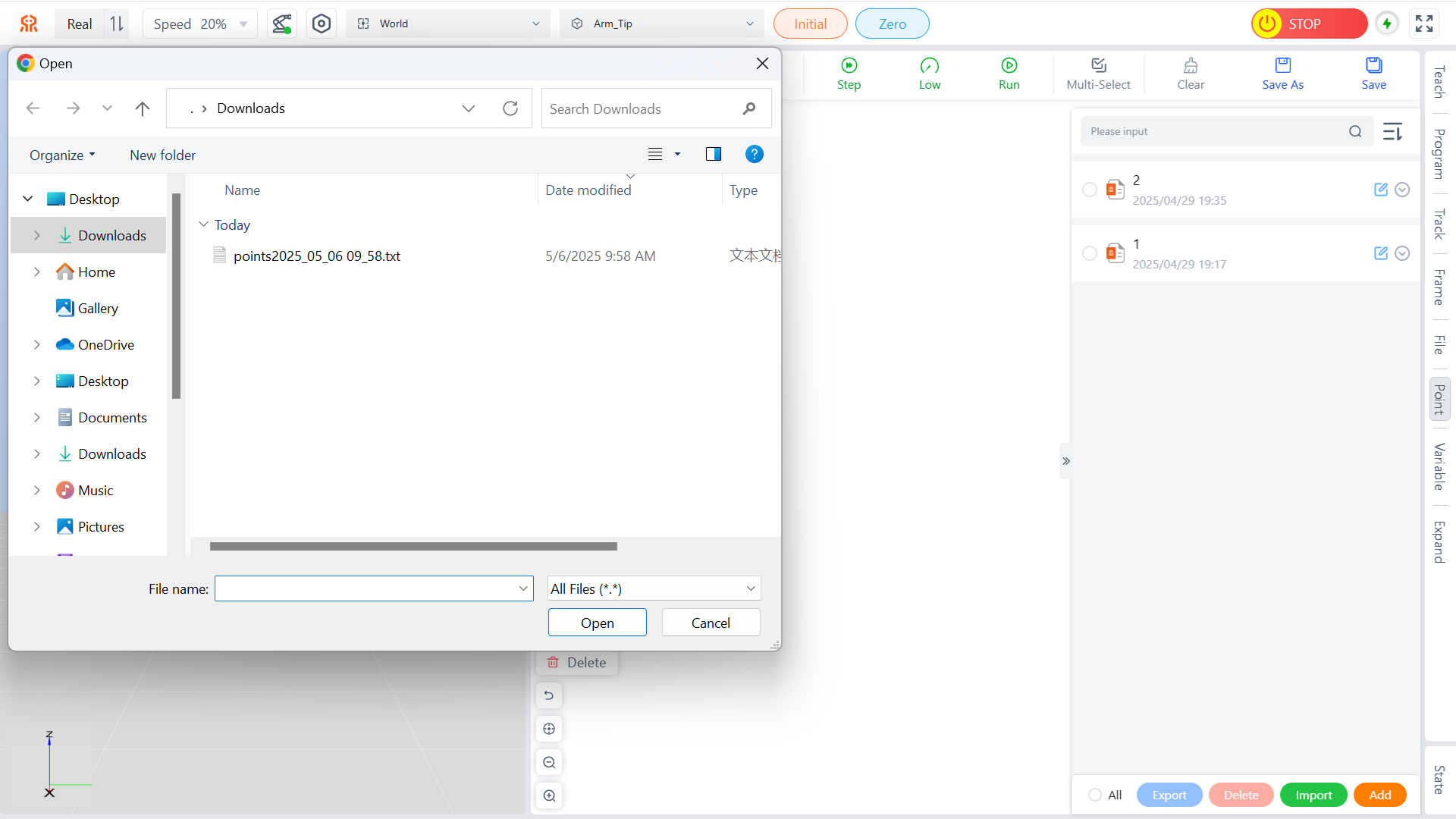
Note: If the imported point file conflicts with a point file in the teaching device, a prompt will appear. Please choose the appropriate handling method and click Confirm to complete the import.
Add
Users can use this feature to add frequently used points. Saved points can be viewed and edited in the point menu, making it convenient for users.
Example of Adding a Point:
Open the
Pointmenu and click theAddbutton below the point list to switch to the teach menu.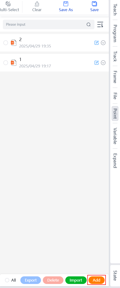
On this page, use the teaching button, pose editing, or end-effector drag teaching button to move the robot arm to the desired position, then click
Saveat the bottom of the page.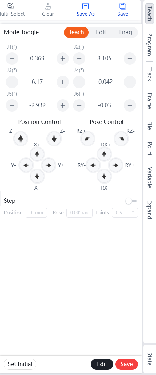
In the pop-up new point dialog box, enter the point name and Comment, then click
Saveto complete the addition of the new point.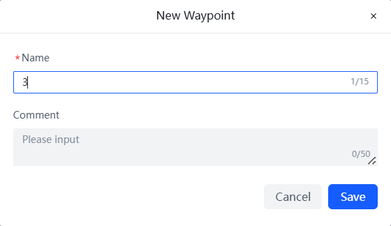
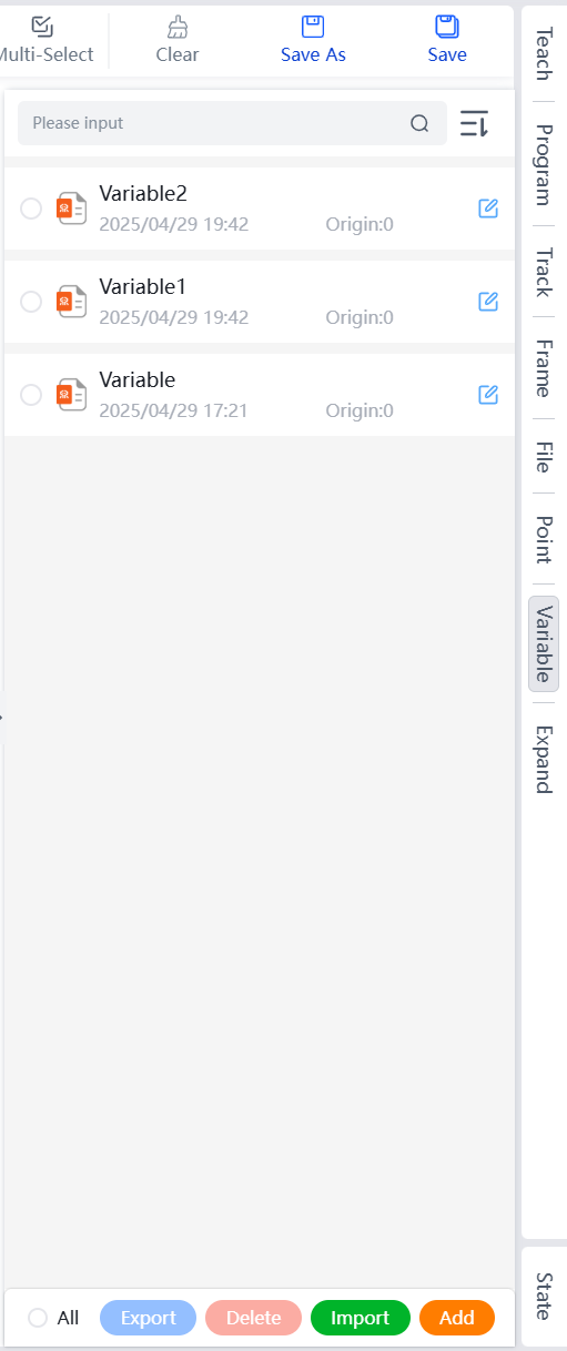
Variable Menu
The variable management page displays variable names, last edit time, and initial values. You can perform Edit, Export, Delete, Import, and Add operations.
- Supports sorting by Chronological, Reverse Chronological, Reversed names, Ordered names, Reversed Size, and Ordered Size.
- Supports precise search by variable name.
Edit
Modify and save variable names and initial values.
In the variable list, click the edit button to the right of the target variable.
In the pop-up edit variable dialog box, enter the modified variable name and initial value, then click
Saveto complete the editing of the variable.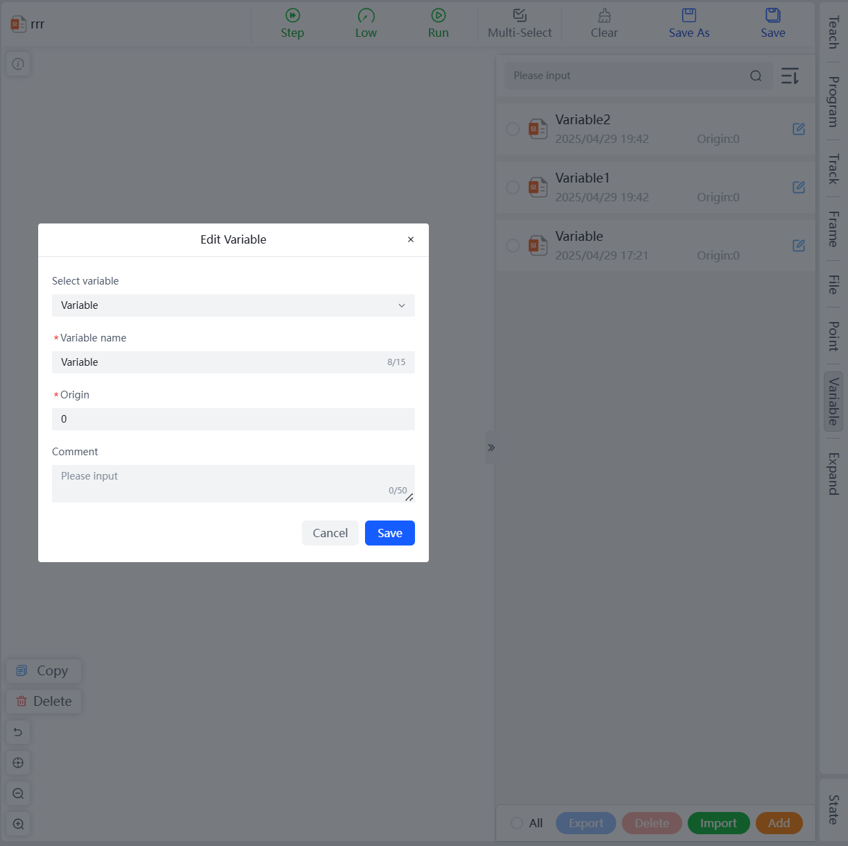
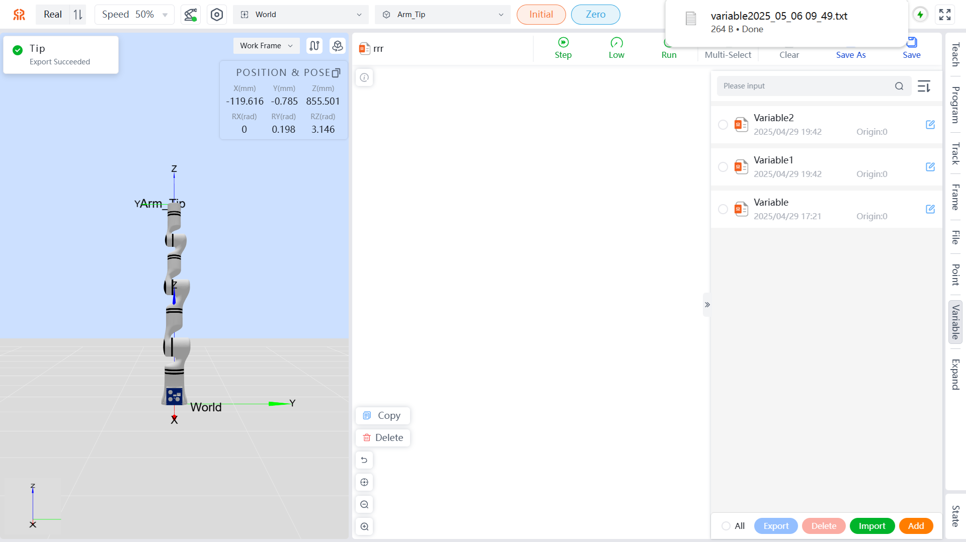
Export
Supports exporting variables to the local system.
Select the variables to be exported. You can select all variables by clicking the All button at the bottom left, then click the Export button to export the variables to the download path set in your browser, with the file extension .TXT.
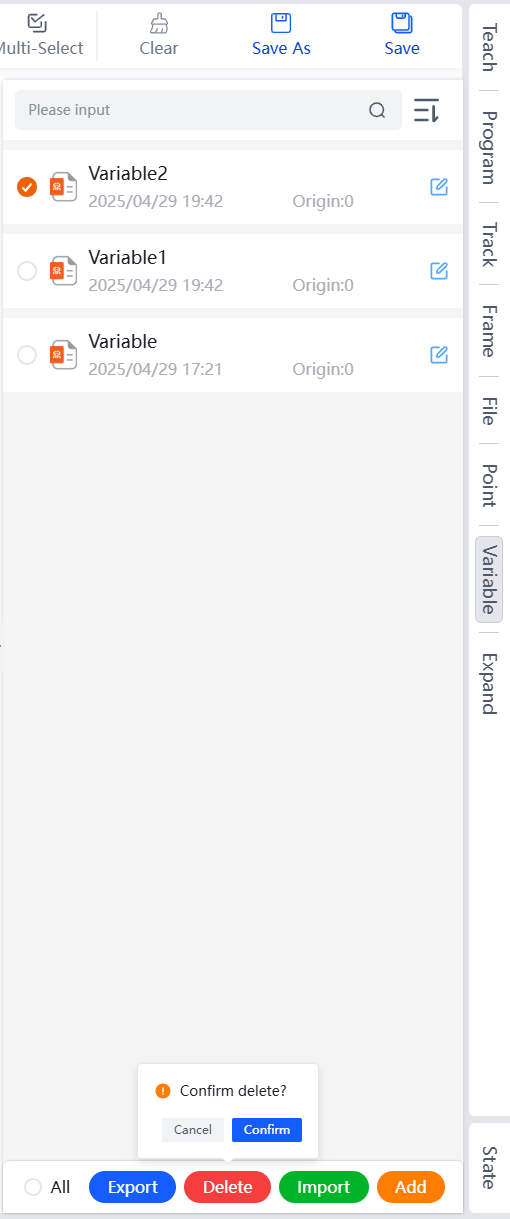
Delete
When a variable is no longer needed, you can delete the corresponding variable.
Select the variables to be deleted, and you can click the All button at the bottom left to select all variables. Then click the Delete button, and in the pop-up confirmation box, click Confirm to complete the deletion of the target variables.
Import
You can import variables from your local storage.
Click the Import button, and in the pop-up dialog, select the target variable file, then click Open to complete the import of variables.
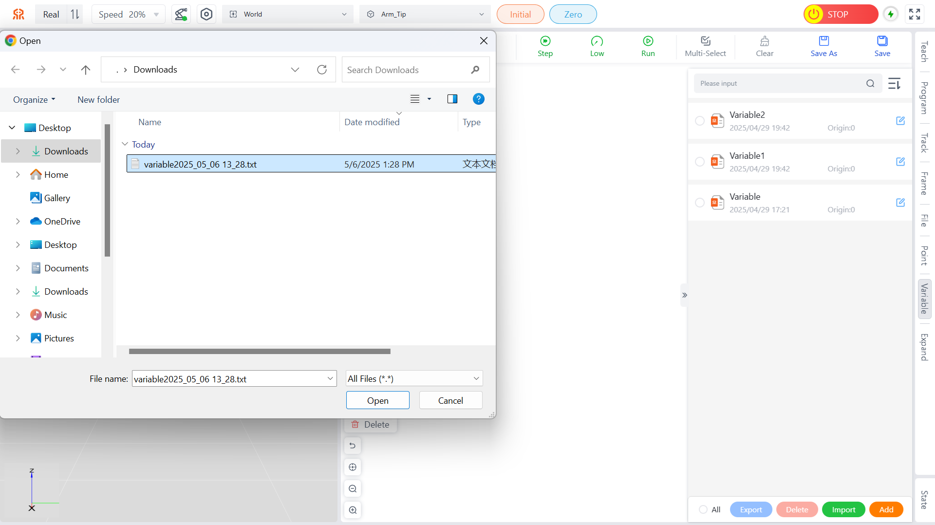
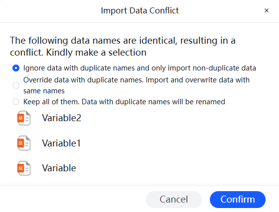
Note: If the imported variables conflict with those in the teaching pendant, a prompt will appear. Please choose the appropriate handling method according to your needs and click Confirm to complete the import.
Add
Used to create new variables.
Click the
Addbutton, and in the pop-up dialog for adding a new variable, enter the variable name and origin value.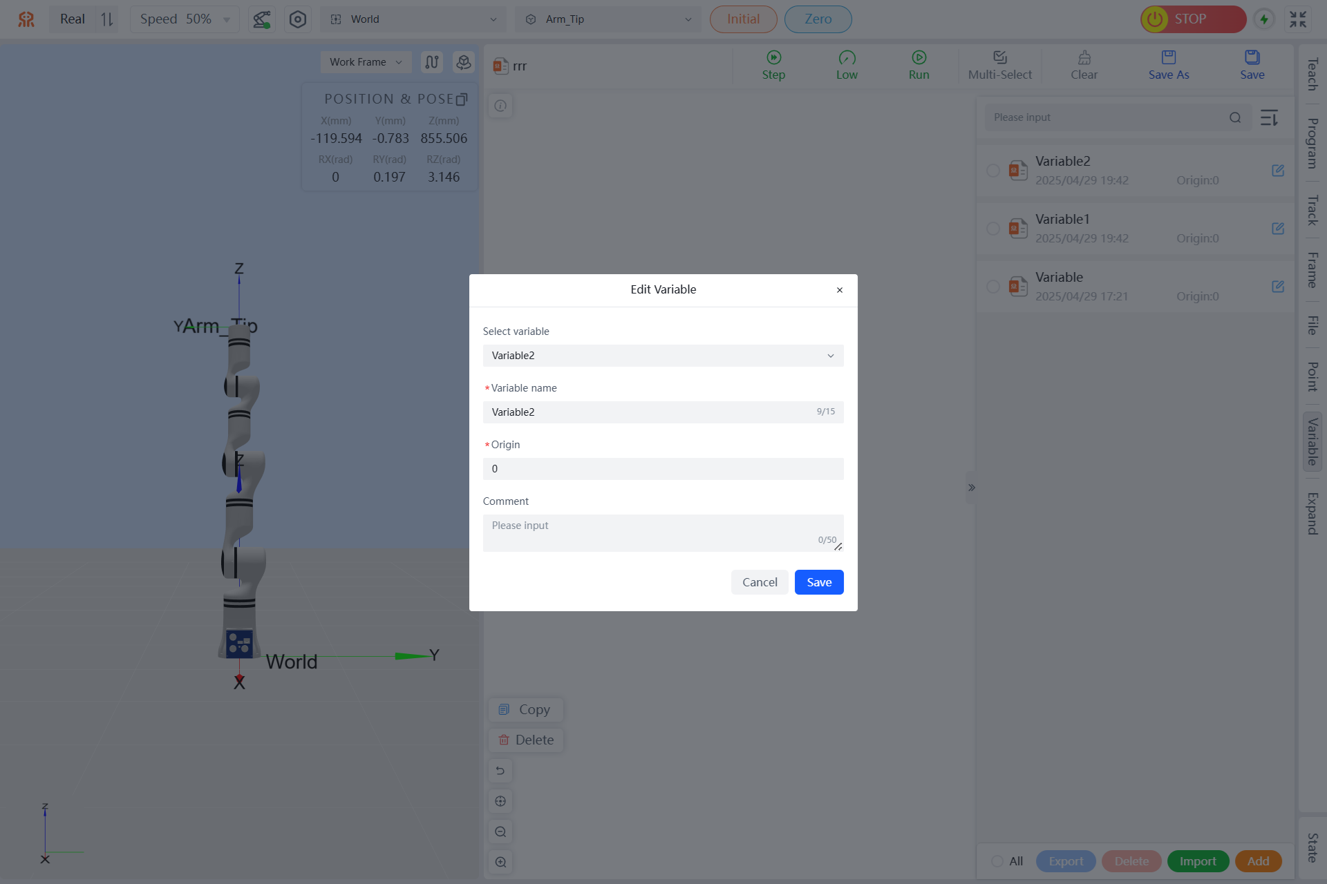
Click
Saveto complete the addition of the new variable.
The newly created programming variable will be automatically added to the variable list.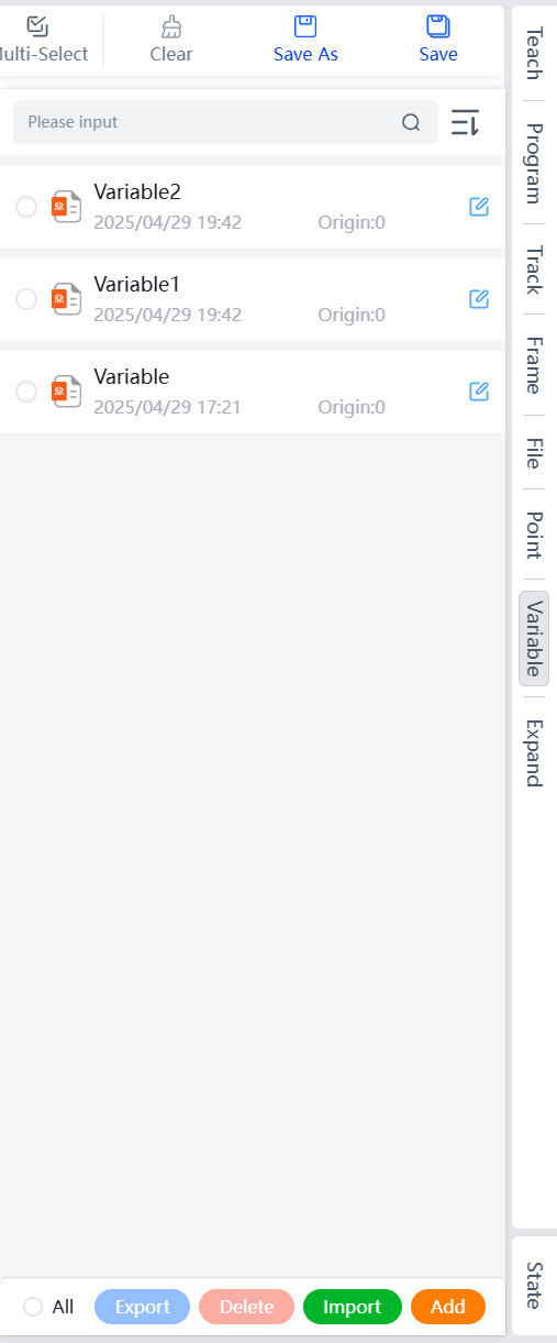
Extended Menu
In the extended interface of the teaching pendant, you can manage the end-effector tools, including switching the output voltage of the tool end and performing simple control of the end-effector gripper. For more details, please refer to Robotic Arm Extension.
State Menu
The status interface on the teaching pendant allows you to view the controller status and joint status, as well as IO and force sensor, etc. It also supports joint control and IO interface configuration. For specific content, please refer to Robot Arm State.