Start guide:
Robot Arm Configuration Basic Configuration
Switch Language
Click the target language button to switch to the desired language, currently supporting Chinese and English.

IP Mode Setting
On the basis of a successful connection between the robot arm and the teaching pendant, you can set the robot arm's IP in the Configuration > Basic Config > IP Mode Setting module.
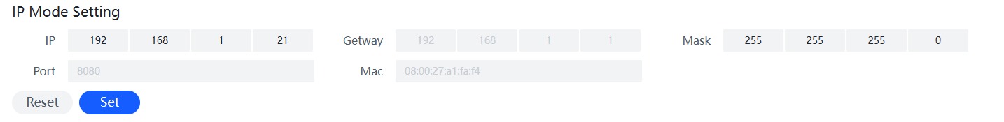
In the teaching pendant's IP mode setting, you can directly set the robot arm's IP by entering it in the IP text box, such as "192.168.1.19". After entering the IP, click the Set button to directly set the robot arm's IP. This setting requires a reboot of the robot arm to take effect. To restore the IP address to "192.168.1.18", click the Reset button, and the robot arm's IP will be restored to "192.168.1.18". This setting also requires a reboot of the robot arm to take effect. (If you have modified the robot arm's IP, you need to enter the updated IP when logging into the teaching pendant interface.)
After clicking the set button, the configured IP will be automatically downloaded. Please save it to avoid forgetting the IP.
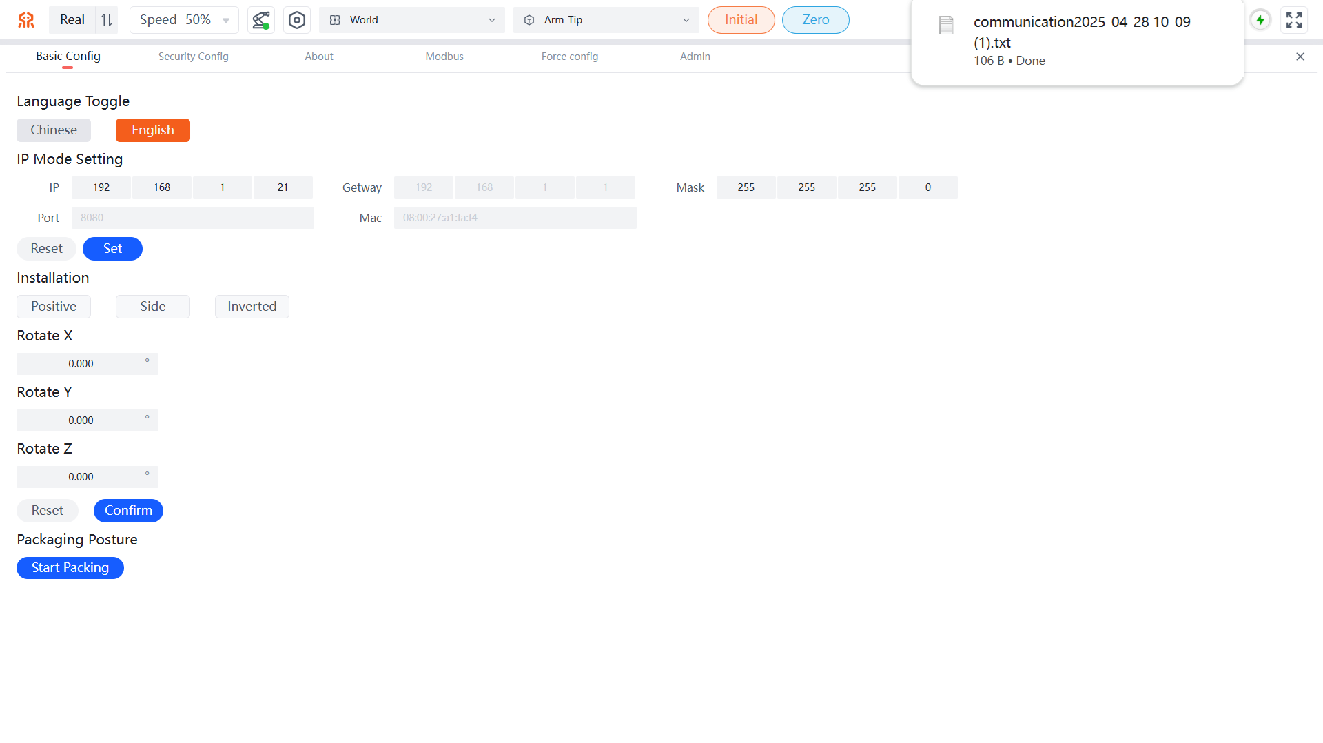
Installation Information
Robot installation information refers to the installation angle settings. In this interface's model window, you can view in real-time whether the set installation angle matches the required angle. Area 1 allows quick setting of common installation directions, including Positive, Side, and Inverted installation. Area 2 allows setting Rotate X, Rotate Y, and Rotate Z for the installation. After setting, click the Confirm button to save.
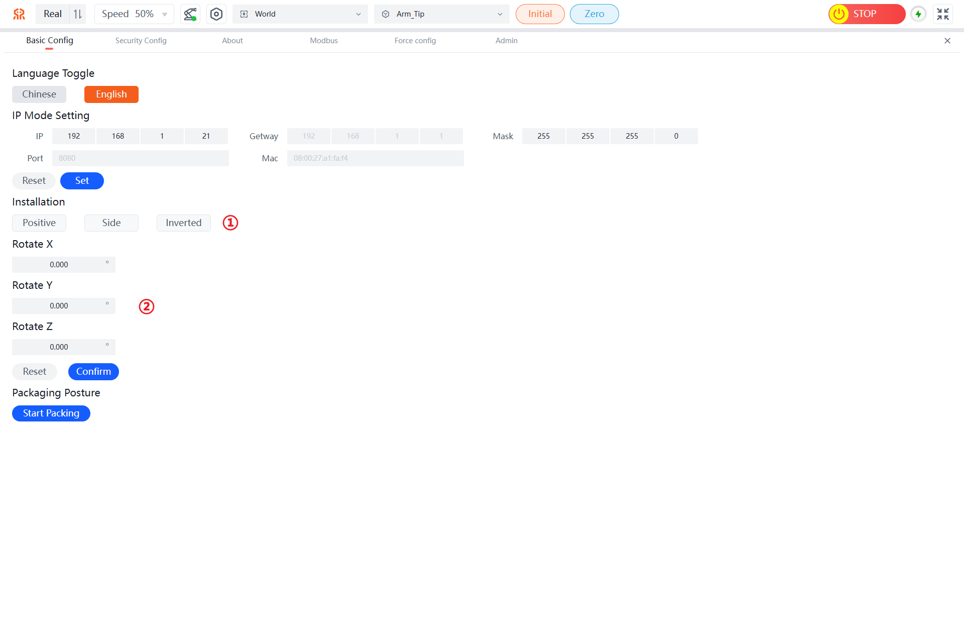
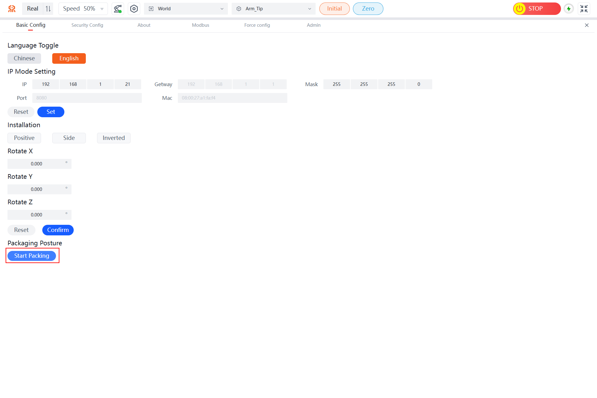
Packing Pose Example
After using the robot, when you need to repackage it, the controller has already saved the robot's packing pose. Long-press the Start Packing button in the packing pose module, and the robot will automatically move to the packing pose. When the robot stops moving, the packing pose is complete.
Security Config
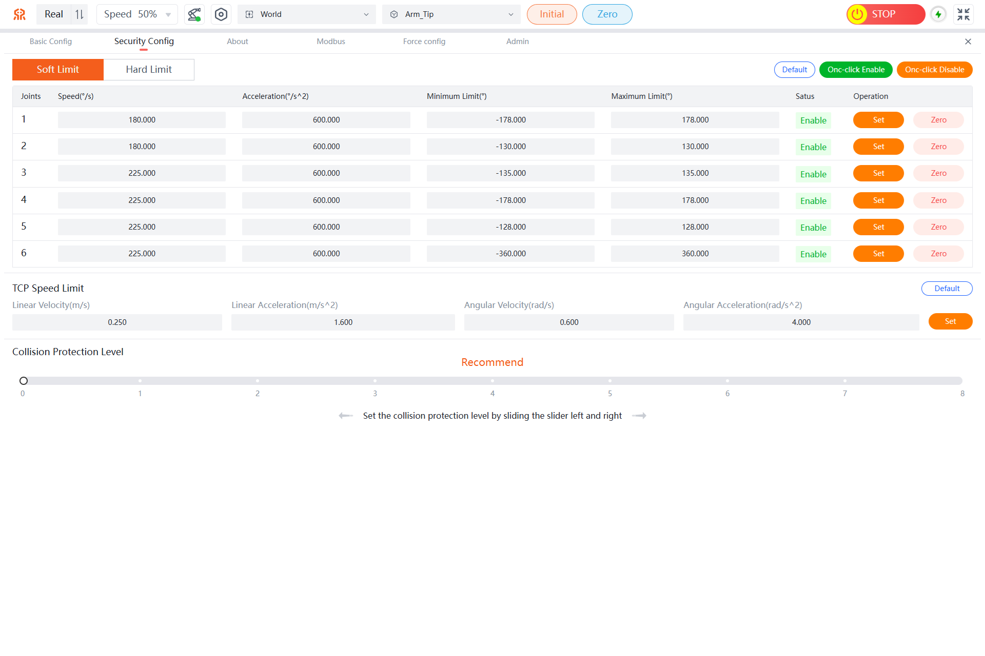
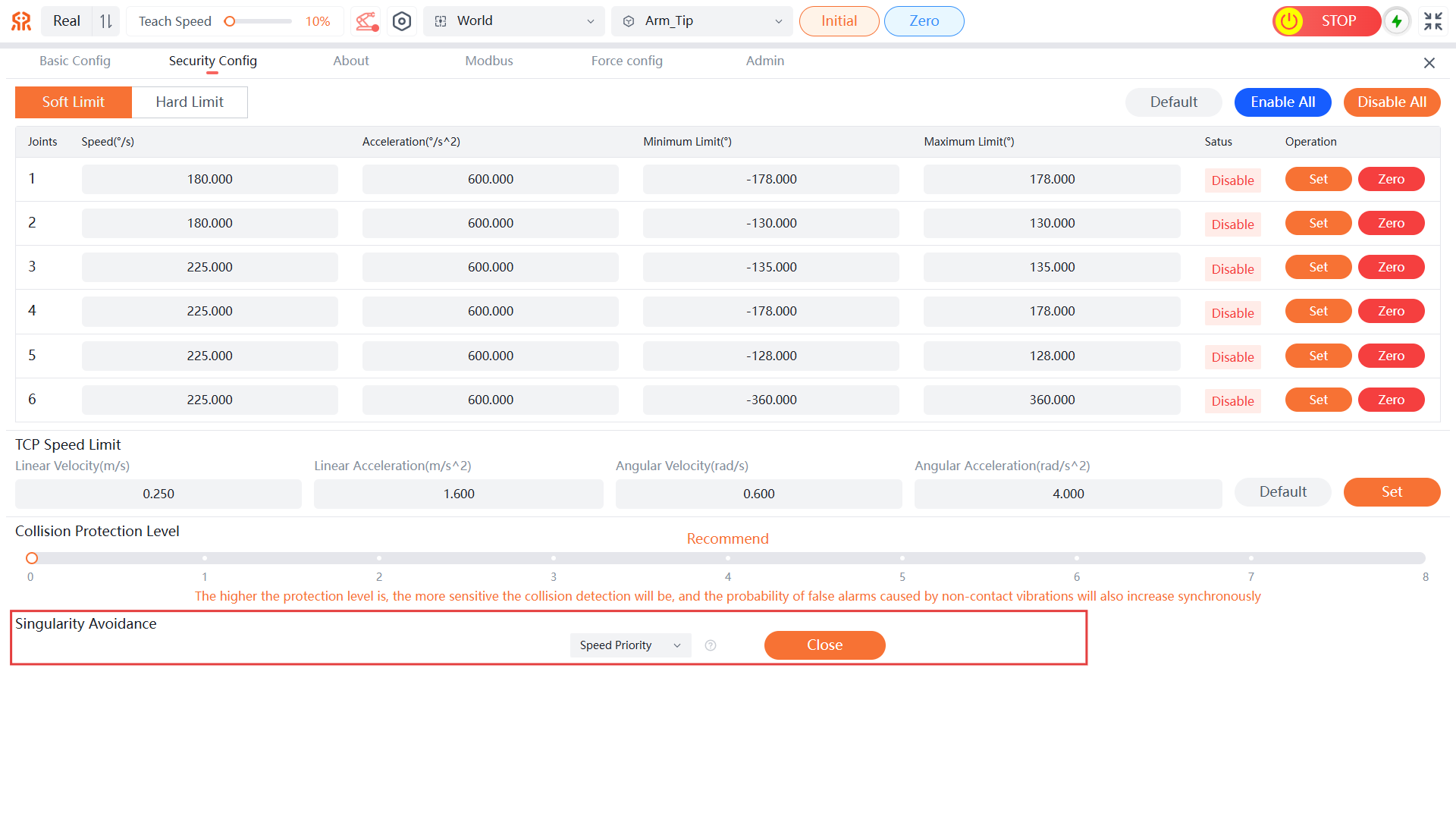
The Security Config interface mainly configures the robot's joints, end-effector TCP speed limits, and Collision protection level parameters. As shown in the following figure:
Joint Configuration
At the top of the page, parameters for joints 1 to 6 are displayed, corresponding to the six joints from bottom to top of the robot. After establishing a connection between the teaching pendant and the robot, the maximum speed, acceleration, minimum limit, maximum limit, and status information of each joint will be automatically displayed in their respective positions.
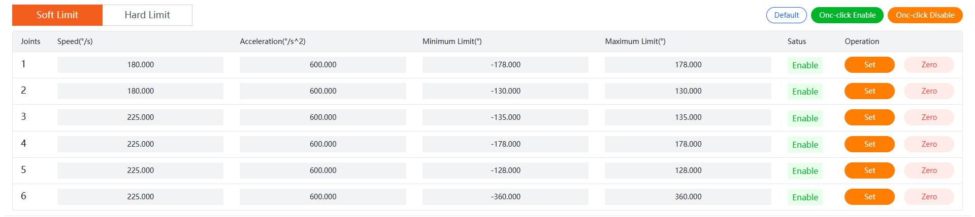
- Speed: The maximum rotational speed of the joint, unit: °/s. Joints 1 and 2 have a maximum of 180°/s, while other joints have a maximum of 225°/s.
- Acceleration: The maximum acceleration of the joint, unit: °/s^2, with a maximum value of 600°/s^2. The default factory value is 600°/s^2, which is the best data for all aspects and is not recommended for user modification.
- Minimum Limit: The minimum position that the joint can reach, unit: degrees.
- Maximum Limit: The maximum position that the joint can reach, unit: degrees.
- Status: The current enabled status of the joint.
- Operation: Supports setting and zeroing operations for joints.
- The
One-click Enablebutton andOne-click Disablebutton send enable and disable commands to all joints, respectively.
Set Joints
WARNING
All parameters of Realman robot arms are configured to their optimal state before leaving the factory, and it is generally not recommended for users to modify the underlying parameters of the joints. If users indeed need to modify them, they should first ensure that the robot arm is in a non-enabled state, then send the parameter modification command. After successfully setting the parameters, send an enable command to the joints. It is important to note that when enabling the joints, users must ensure that the joints are in a stationary state to prevent positioning errors during the enable process. After normal joint enablement, users can control joint movement. When modifying, the ratio of the maximum acceleration to the maximum speed of the joint should be ≥1.5 times; otherwise, abnormal movement may occur.
- Refer to Disable to complete joint 1 disable.
- Modify joint 1's maximum speed, acceleration, minimum limit, and maximum limit parameters as needed.
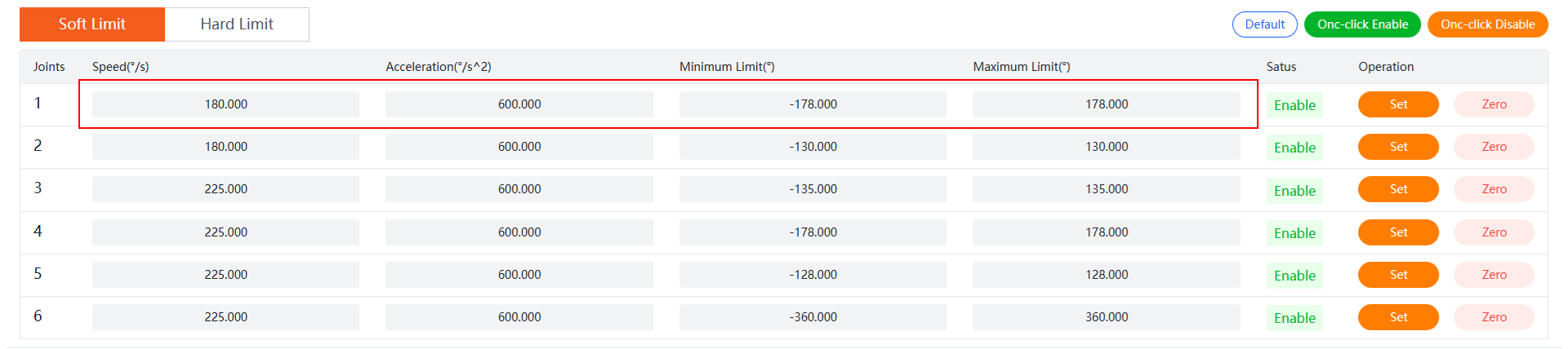
- Click the
Setbutton in joint 1's operation column to complete parameter settings for joint 1. - Refer to Enable to complete joint 1 enable.
Zero
Introduction:
When a joint is in a disabled state, clicking the Zero button sets the current position of the specified joint as zero position. After setting, the joint remains in a disabled state. Clicking the Enable button re-enables the joint so that it can be controlled.
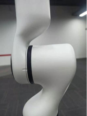
Each joint of the robot has a mechanical origin position (as shown in the figure below). The zero position pose is the pose where all joints are at the robot's origin position. When the robot is in its zero position pose and the mechanical origin position markers are misaligned, you need to manually set the robot back to its mechanical origin position. The state of the robot when it is in its zero position pose is shown in the following figure:
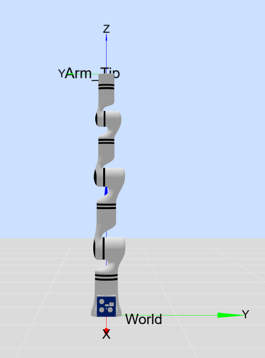
When replacing a robot joint, you must re-set the zero position for the corresponding joint.
WARNING
Not all robots support this feature. Please confirm with Realman Intelligent Technology (Beijing) Co., Ltd. before setting it up.
Operation Steps:
This article uses setting the zero position of Joint 1 as an example (setting the zero position for other joints can also refer to this).
- Refer to Disable to complete the drop enable for Joint 1.
- Rotate Joint 1 to the mechanical origin position (where the grooves on both sides of the joint gap are perfectly aligned, which is the mechanical origin position).
- Click the
Zerobutton in the operation column of Joint 1, and clickConfirmin the pop-up dialog box to complete the zero position setting for Joint 1. - Refer to Enable to complete the enable for Joint 1.
TCP Speed Limit
This section mainly sets the Linear Velocity, Linear Acceleration, Angular Velocity, and Angular Acceleration of the robot's end-effector. After the teaching pendant establishes a network connection with the robot controller, this section will automatically update the current TCP parameters of the robot. Users can manually modify the parameters and send them.
Click the Default button to restore the robot's TCP parameters to their default values. End-effector Linear Velocity: 0.250m/s, Linear Acceleration: 1.600m/s², Angular Velocity: 0.600rad/s, Angular Acceleration: 4.000rad/s².
WARNING
It is recommended to use the default TCP speed. If changes are needed, the ratio of the maximum acceleration to the maximum speed of the robot's end-effector should be ≥3; otherwise, abnormal movements may occur.
Collision Protection Level
This section mainly sets the collision level of the robot, with levels ranging from 0 to 8, representing the sensitivity levels of collision detection. The higher the level, the more sensitive the robot is to collisions. The default collision level when the robot is powered on is 0, meaning no collision detection is performed.

WARNING
When setting the collision protection level, users should choose reasonably. The higher the level, the higher the probability of false collision detection. If there are no special requirements, it is recommended to set the collision level around 4. Additionally, if the tool and load at the robot's end-effector change, the tool's mass and center of mass parameters should be set during Tool Coordinate System Calibration (Tool Coordinate System Calibration) to match the correct dynamic model.
Singularity Avoidance
Currently, singularity avoidance is only supported in the `Speed-Priority mode. Under this mode, during the trajectory operation, the robotic arm will change the posture of some joints near the singularity to avoid it, maintaining the movement speed. However, the trajectory accuracy will be somewhat reduced near the singularity.
WARNING
- The singularity avoidance is turned off by default.
- Singularity avoidance has no effect on teaching.
- For scenarios requiring precise trajectories, it is not recommended to use singularity avoidance, as it automatically modifies the trajectory.
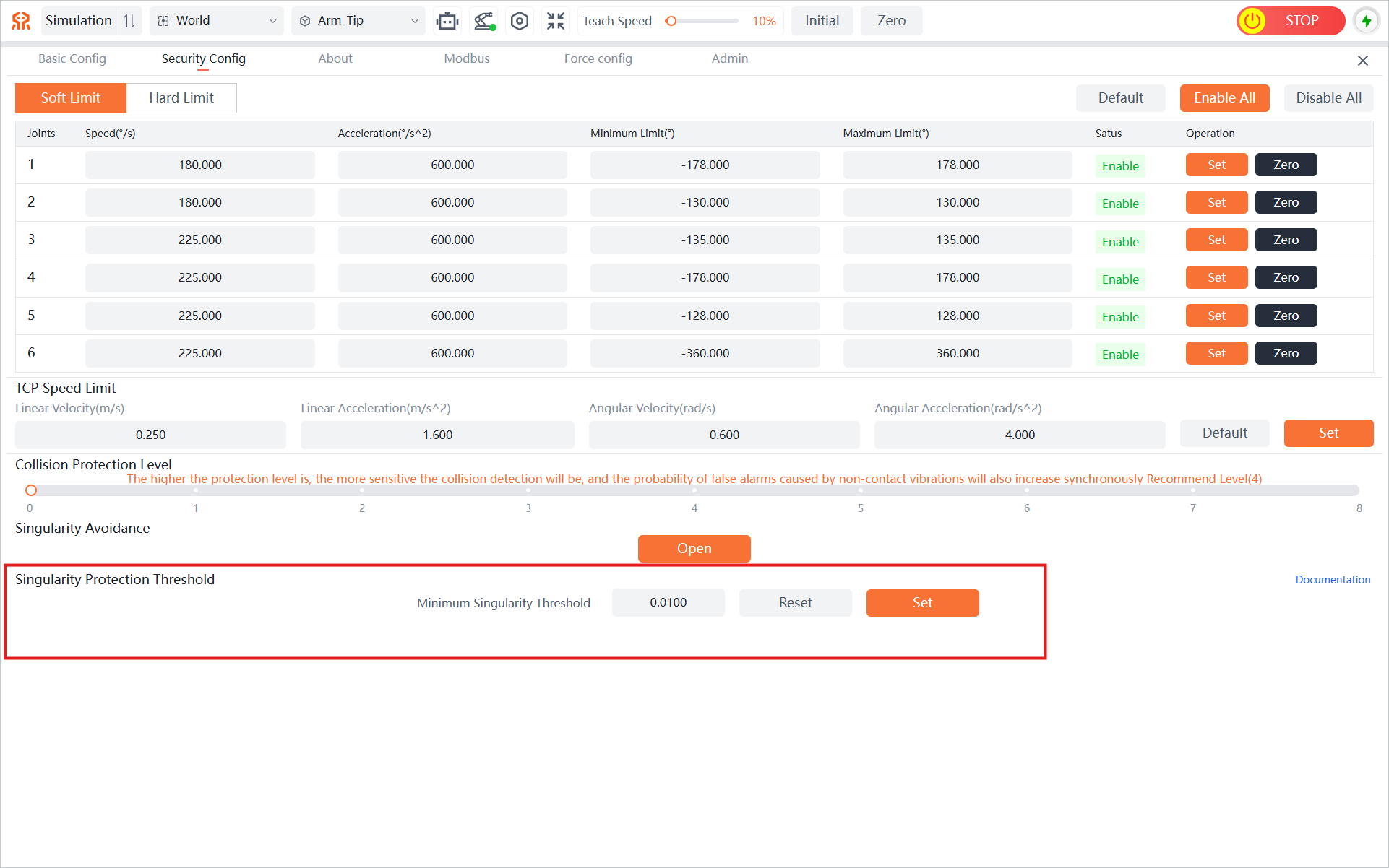
Singularity Protection
To ensure the safe movement of the robotic arm, a unified singularity detection and protection mechanism is implemented. This mechanism quantifies the arm’s manipulability by real-time calculating the minimum singular value of the Jacobian matrix for the current configuration. When the detected manipulability falls below the safety threshold, the system will trigger an emergency stop to prevent the equipment from entering an uncontrollable singular state. The default value of the minimum singularity threshold is 0.01; for parameter adjustment instructions, refer to Parameter Tuning Instructions for Robot Arm Singularity Threshold.
Tool Calibration System Calibration
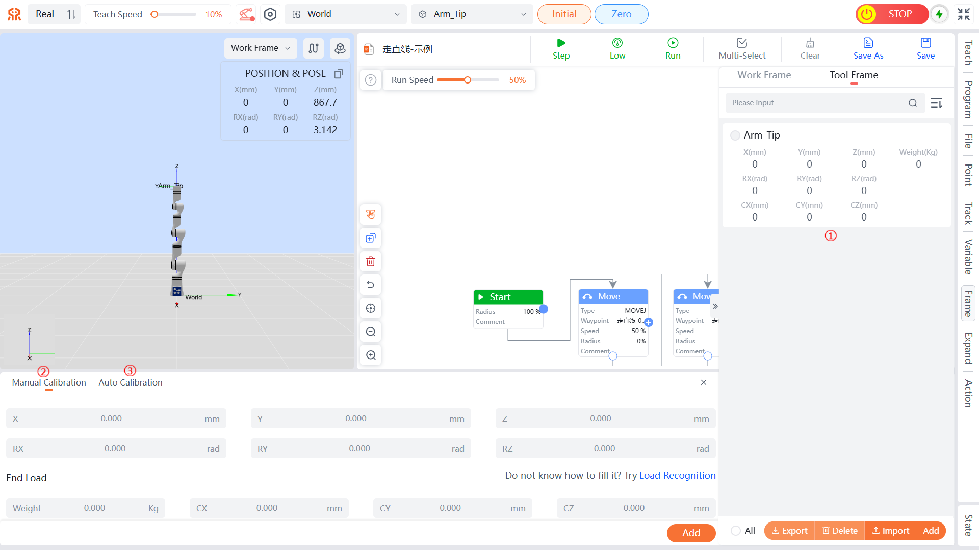
The tool calibration is as shown in the following figure. Zone 1 displays all current tool coordinate and tool pose information, zone 2 involves manual setting of Tool Frame information, and zone 3 involves auto calibration of the current Tool Frame.
Tool Calibration Display
All the Tool Frame names and pose parameters established by the current robot are displayed on the right side of the page. To delete a tool, select it and click the Delete button. After the tool is deleted, the robot enters the end flange coordinate to work. In addition, Arm_Tip (robot end tool coordinate) cannot be deleted.
Manual Calibration
When the user knows the accurate relative pose of the tool relative to the center of the robot's end flange, the Tool Frame can be directly set by manually entering information.
On the
Frame > Tool Framepage, clickAddat the bottom right of the page; theManual Calibrationconfiguration page will open by default.On the
Manual Calibrationconfiguration page, define the information of X, Y, Z, RX, RY, and RZ.On the
Manual Calibrationconfiguration page, define theEnd Loadinformation. Load Recognition is supported viaAuto IdentificationandManual Identification.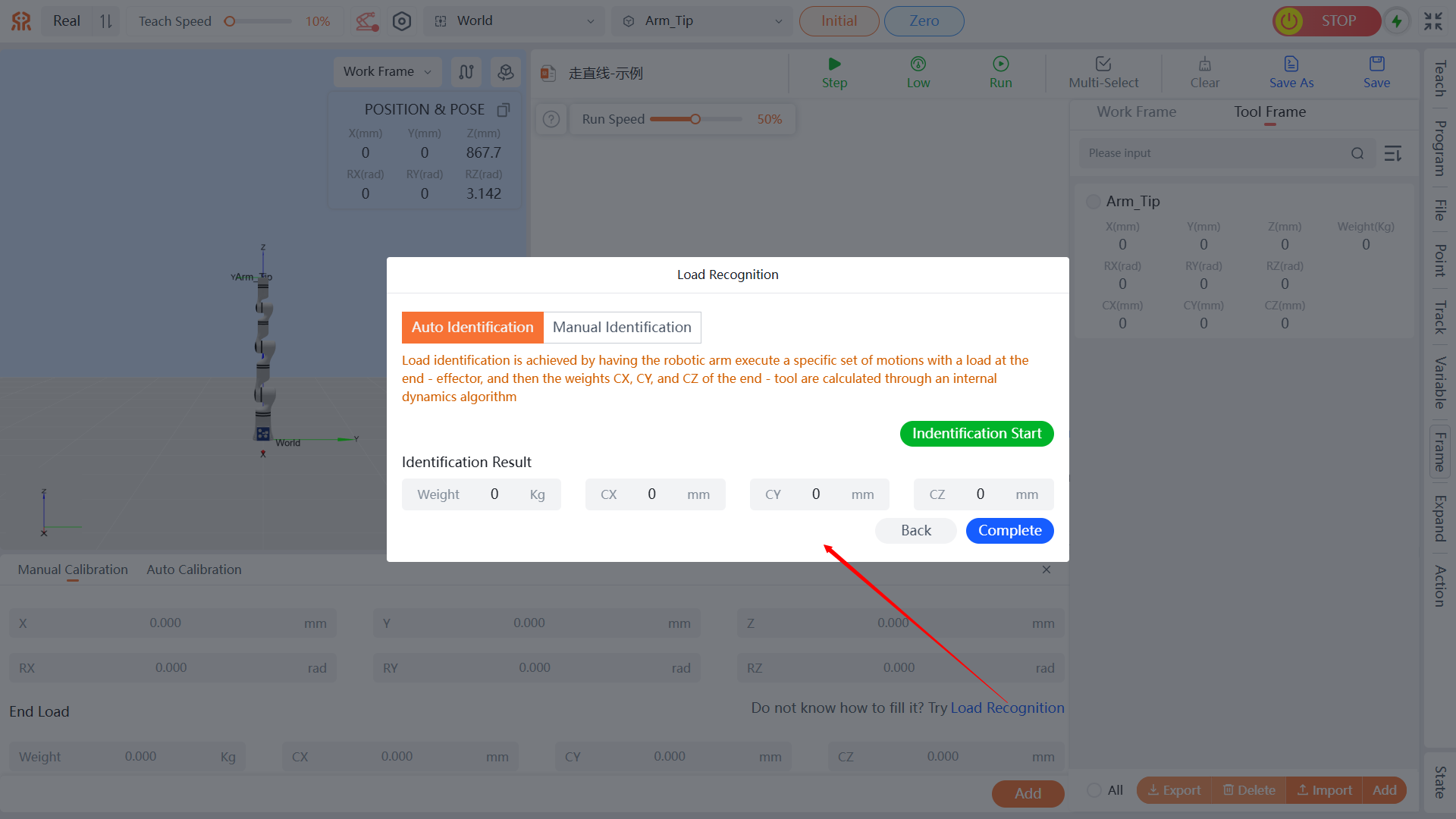
- Auto Identification: Execute the set of end poses specified by default for the robotic arm, and directly click
Identification Startto perform auto load identification. - Manual Identification: Manually specify four end poses of the robotic arm. The end poses of the four points need to have as large a variation as possible—the larger the variation, the more accurate the identification result. If the variation is too small, identification may fail. After setting the end poses, click
Identification Startto perform load identification. - After identification is completed, click
Completeat the bottom right of the dialog box.
- Auto Identification: Execute the set of end poses specified by default for the robotic arm, and directly click
Note
- Load Identification: Load identification is achieved by having the robotic arm execute a specific set of motions with a load at the end - effector, and then the weights CX, CY, and CZ of the end - tool are calculated through an internal dynamics algorithm. A deviation of approximately 0.5kg between the finally calculated end load and the actual weight obtained by weighing is normal.
- If the end fixture is relatively long, it may collide with the robotic arm during the load identification movement.
- After defining the information, click
Addat the bottom of the page. In the pop-up dialog box, define theNameinformation to complete the addition of the Tool Frame calibration. The newly added Tool Frame calibration will be displayed in the list on the right side of the page.
Auto Calibration
The current Tool Frame can be calibrated using the six-point method.
On the
Frame > Tool Framepage, clickAddat the bottom right of the page, then click theAuto Calibrationtab to open theAuto Calibrationconfiguration page.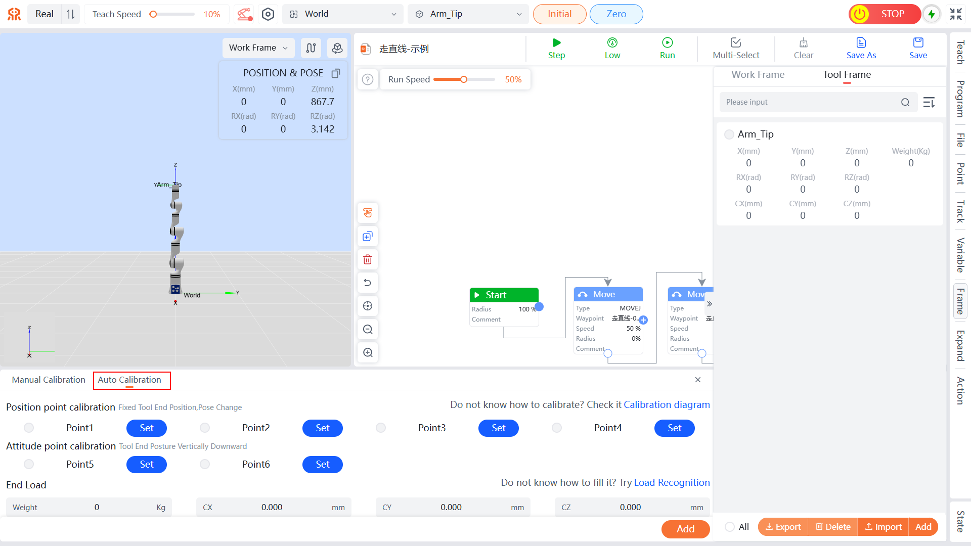
Define the
Position Point CalibrationandAttitude Point Calibrationinformation: Bring the robot tool into contact with the tool reference point (the reference point requires a sharp end and should be placed vertically upward within the robot's working range) in 6 different attitudes respectively.The calibration rules for the six-point method are as follows:
| Serial Number | Name |
|---|---|
| 1 | 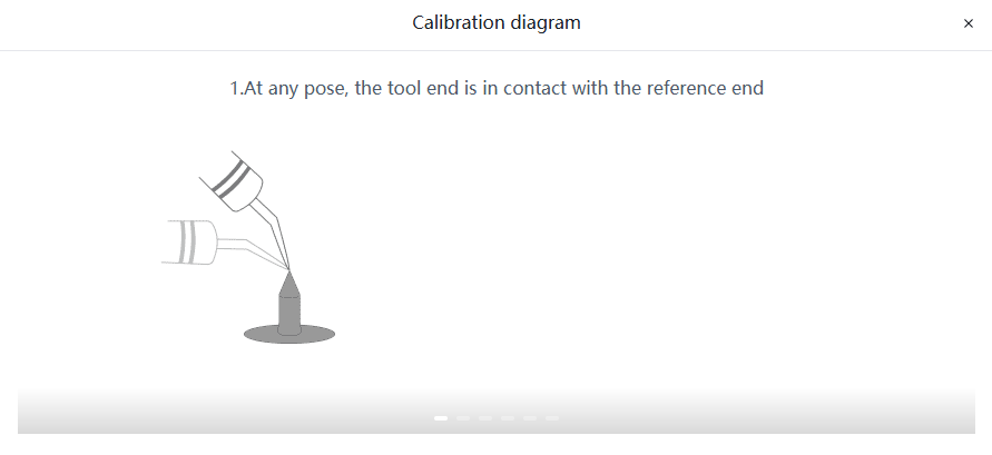 |
| 2 | 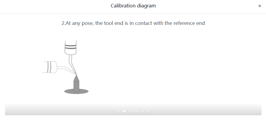 |
| 3 | 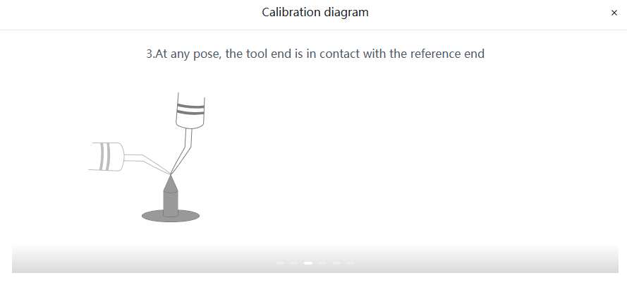 |
| 4 | 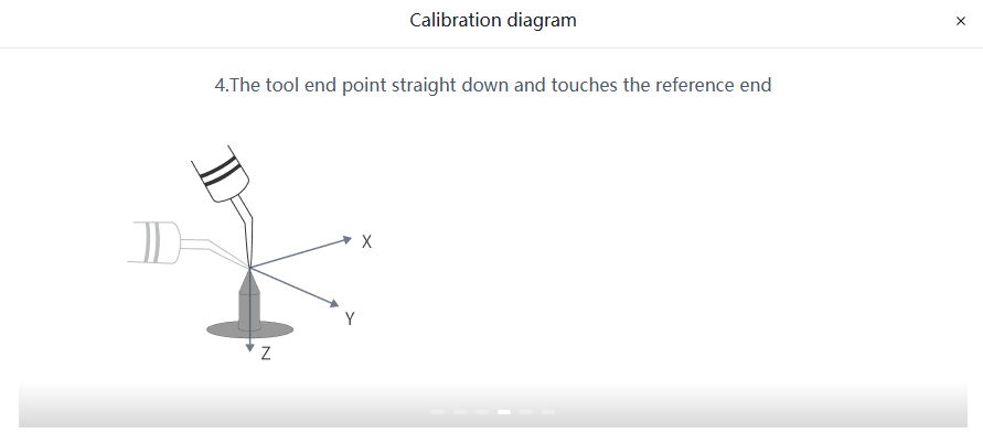 |
| 5 | 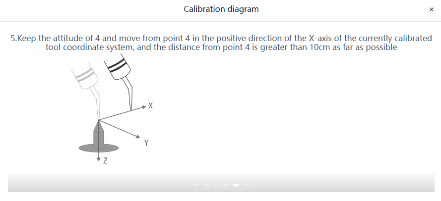 |
| 6 | 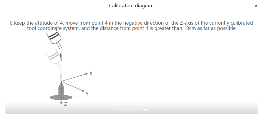 |
Caution
The attitude difference between the first 4 points should be as large as possible; do not select identical points.
Define the
End Loadinformation. Load Recognition is supported viaAuto IdentificationandManual Identification.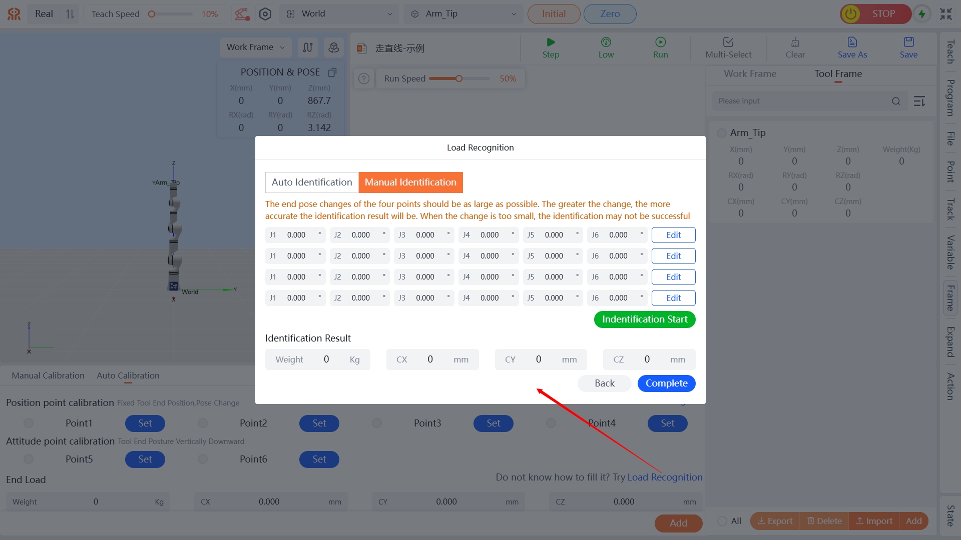
- Auto Identification: Execute the set of end poses specified by default for the robotic arm, and directly click
Identification Startto perform auto load identification. - Manual Identification: Manually specify four end poses of the robotic arm. The end poses of the four points need to have as large a variation as possible—the larger the variation, the more accurate the identification result. If the variation is too small, identification may fail. After setting the end poses, click
Identification Startto perform load identification. - After identification is completed, click
Completeat the bottom right of the dialog box.
- Auto Identification: Execute the set of end poses specified by default for the robotic arm, and directly click
Note
- Load Identification: Load identification is achieved by having the robotic arm execute a specific set of motions with a load at the end - effector, and then the weights CX, CY, and CZ of the end - tool are calculated through an internal dynamics algorithm. A deviation of approximately 0.5kg between the finally calculated end load and the actual weight obtained by weighing is normal.
- If the end fixture is relatively long, it may collide with the robotic arm during the load identification movement.
- After defining the information, click
Addat the bottom of the page. In the pop-up dialog box, define theNameinformation to complete the addition of the Tool Frame calibration. The newly added Tool Frame calibration will be displayed in the list on the right side of the page.
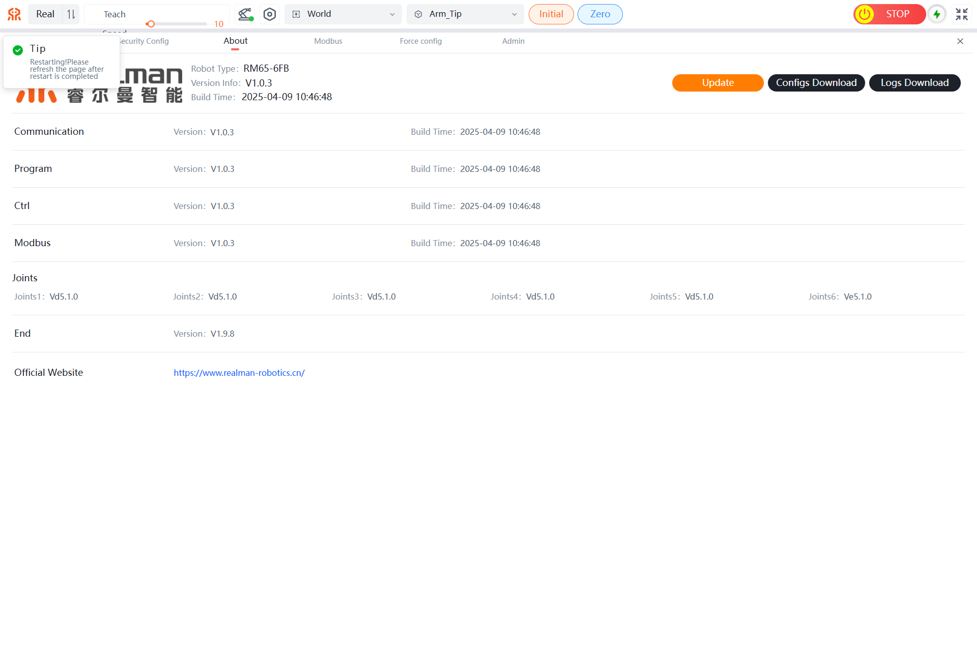
About
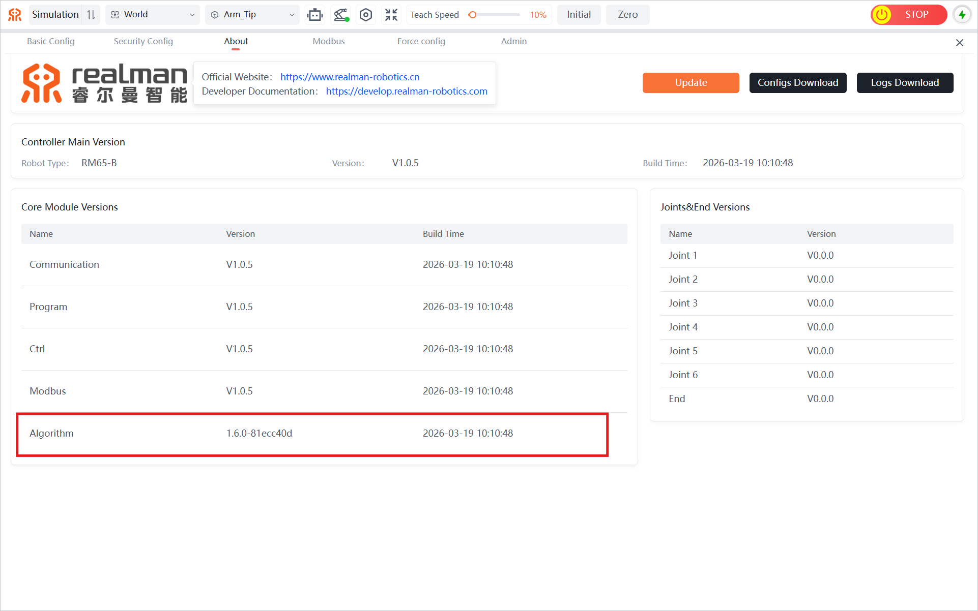
The About page displays the following information for the teaching pendant and supports operations such as Update, Configs Download, and Logs Download.
- Robot Type, Version Info, and Build Time;
- Communication, Program, Ctrl, Modbus, and Algorithm versions and build times;
- Software versions of each joints.
- End-effector interface board version.
- Official Website: https://www.realman-robotics.cn/.
Update
The system program of the robot controller can be upgraded by clicking the Configuration button on the teaching pendant and selecting the About tab on the configuration page (before upgrading, please confirm whether the corresponding version can be upgraded, otherwise serious problems may occur).
The specific operation steps are as follows:
- Download the file with a .realman extension provided by the manufacturer to your local machine.
- Click the
Updatebutton, find and select the file saved in step 1 in the pop-up window. After a successful selection, file parsing will begin.

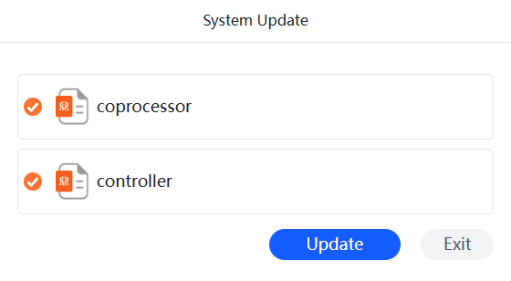
- After file parsing is complete, a list of selected update files will pop up. Choose the files you need to update (all files are selected by default), click the
Updatebutton, and begin the update.
- Wait for the update to complete (the update time may take 4-5 minutes for large files; please be patient).
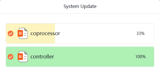
- When all progress is successfully updated, the interface will display that the update is complete.
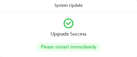
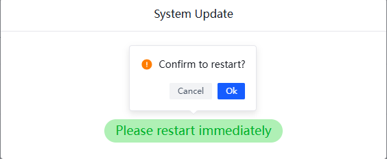
- Click
Please restart immediately, and in the pop-up dialog box, clickOKto restart the robot.
- After restarting, the robot can operate normally.
WARNING
Precautions for updating controller programs: After updating the robot program, restart the robot and open the WEB teaching pendant. After entering the home page of the teaching pendant, press Ctrl+F5 to force a browser refresh and clear the cache. At this point, both the updated robot and WEB teaching pendant can be used normally.
Configs Download
When you need to download a configuration file, please follow these steps. The configuration file mainly includes parameter configuration information for the current robot.
- Click the
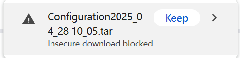
Configurationbutton to enter the configuration page. - Select the
Abouttab, clickConfigs Download, and the system will automatically start packaging and download the teaching pendant configuration file.。

Logs Download
When you need to download logs, please follow the steps below. The logs mainly include all operation commands of the teaching pendant and various error codes, along with timestamps.
- Click the
Configurationbutton to enter the configuration page. - Select the
Abouttab, clickLogs Download, and the system will automatically start packaging and download the teaching pendant log.
Modbus
The robotic arm can directly call the programming files saved by the WEB teaching pendant via the MODBUS-TCP protocol, or directly control or query the status of the robotic arm. The specific operation methods are as follows.
The Modbus function is divided into Controller(485), End(485), and ModbusTCP. Users can complete a series of Modbus settings by selecting the corresponding tabs.
Controller(485)
The robotic arm can query the status of the robotic arm through the Controller(485).
- Type: Supports selecting JSON Mode, Modbus-RTU(Controller Master), and Modbus-RTU(Controller Slave) types.
- Baud Rate: Supports selecting seven baud rates: 9600, 19200, 38400, 57600, 115200, 230400, and 460800.
- Query: You can set query parameters as needed, including Mode, Address, Device, Length, and Polling.
- Mode: You can query data from different modes of the robotic arm, including Coil Output, Holding Register, Input Register, and Discrete Input. The Coil Output and Holding Register modes support writing parameter values.
- Address: Set the starting address of the query register to display only the register data after the starting address. The default is 0.
- Device: Set the address of the peripheral device to be queried. The default is 1.
- Length: Set the address length of the query register to display only the corresponding length of register data after the starting address. The default is 100, with a range of 1-100.
- Polling: Set the polling time for querying registers. The default is 0, with a range of 1-10, and can be set to three decimal places.
- Base Select: In the query results of the registers, you can switch the display format of the data as needed. Currently, it supports Decimal (Unsigned), Decimal (Signed), and Hexadecimal formats.
Getting Controller(485) Parameter Values
In the Controller(485) tab, select the Type and Baud Rate in sequence, then click Set. Next, select the Mode and set the Address, Device, Length, and Polling. Click Query to query the current data of the robotic arm. For specific address parameter value descriptions, please refer to the Modbus Slave Address Table of the RM Robotic Arm.
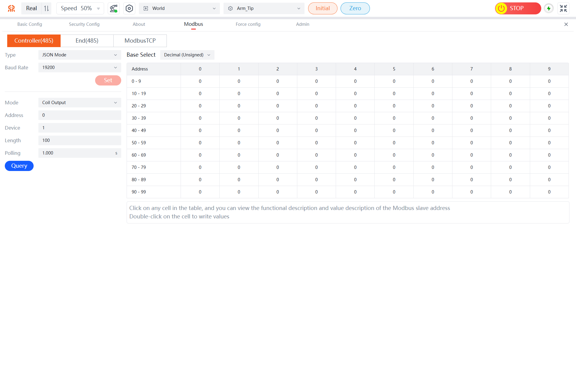
Note: Click any cell in the table to view the function description and value description of the Modbus slave address; in the Coil Output and Holding Register models of the Modbus master type, you can double-click a cell to write a value.
End(485)
The robotic arm can query the status of the robotic arm through the End(485).
- Type: Supports selecting Modbus-RTU(End Master), Hand Mode, and Gripper Mode.
- Baud Rate: Supports selecting three baud rates: 9600, 115200, and 460800.
- Query: You can set query parameters as needed, including mode, address, device, length, and polling.
- Mode: You can query data from different modes of the robotic arm, including coil output, holding register, input register, and discrete input. The coil output and holding register modes support writing parameter values.
- Address: Set the starting address of the query register to display only the register data after the starting address. The default is 0.
- Device: Set the address of the peripheral device to be queried. The default is 1.
- Length: Set the address length of the query register to display only the corresponding length of register data after the starting address. The default is 100, with a range of 1-100.
- Polling: Set the polling time for querying registers. The default is 0, with a range of 1-10, and can be set to three decimal places.
- Base Select: In the query results of the registers, you can switch the display format of the data as needed. Currently, it supports decimal (unsigned), decimal (signed), and hexadecimal formats.
Getting End(485) Parameter Values
In the End(485) tab, select the type and baud rate in sequence, then click Set. Next, select the mode and set the address, device, length, and polling. Click Query to query the current data of the robotic arm. For specific address parameter value descriptions, please refer to the Modbus Slave Address Table of the RM Robotic Arm.
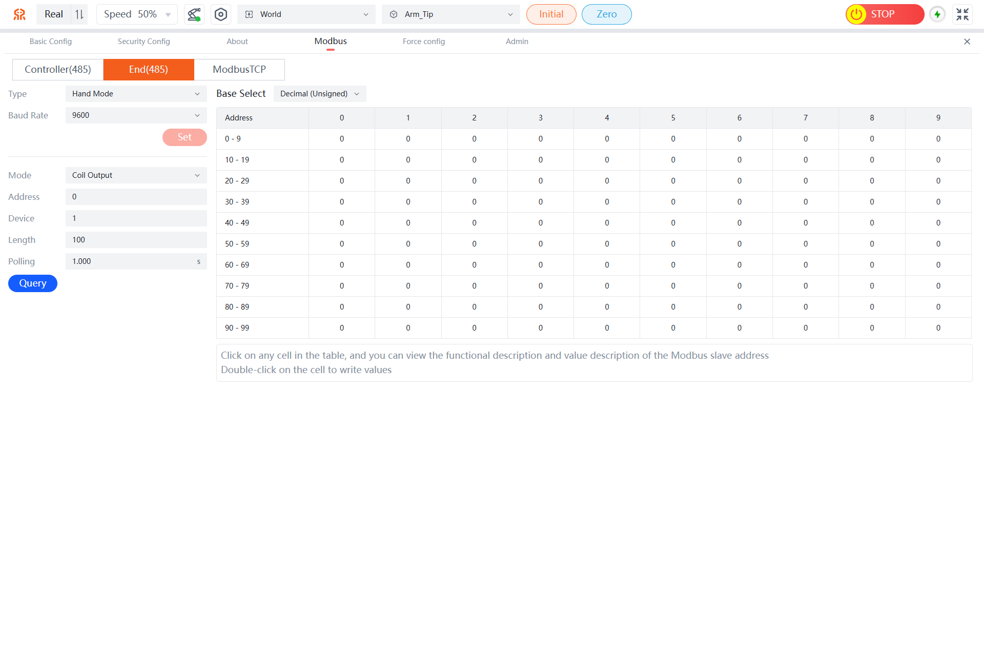
Note: Click any cell in the table to view the function description and value description of the Modbus slave address; in the coil output and holding register models of the Modbus master type, you can double-click a cell to write a value.
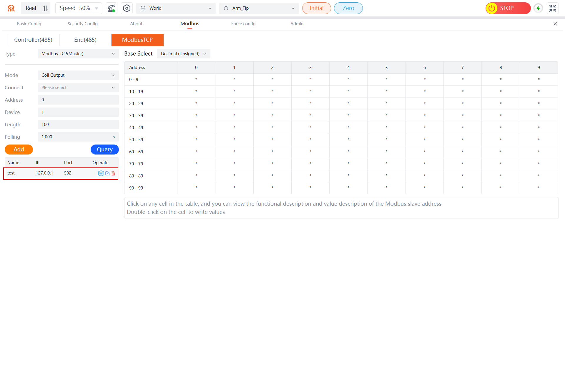
ModbusTCP
The robotic arm can directly control or query its status via the Modbus-TCP protocol.
- Type: Supports selecting Modbus-TCP(Master) and Modbus-TCP(Slave) types.
- Query/Write: You can set query parameters as needed, including mode, connect (supported only by Modbus-TCP master type), address, device, length, and polling.
- Mode: You can query data from different modes of the robotic arm, including coil output, holding register, input register, and discrete input. The coil output and holding register modes support writing parameter values.
- Connect: Select an added Modbus-TCP master station.
- Address: Set the starting address of the query register to display only the register data after the starting address. The default is 0.
- Device: Set the address of the peripheral device to be queried. The default is 1.
- Length: Set the address length of the query register to display only the corresponding length of register data after the starting address. The default is 100, with a range of 1-100.
- Polling: Set the polling time for querying registers. The default is 0, with a range of 1-10, and can be set to three decimal places.
- Base Select: In the query results of the registers, you can switch the display format of the data as needed. Currently, it supports decimal (unsigned), decimal (signed), and hexadecimal formats.
- Modbus-TCP Master Station List: Displayed only for Modbus-TCP master type. You can add multiple master station information via the
Addbutton and perform ping tests, editing, and deletion operations.- Ping: Test the connection status of the master station.
- Edit: Modify the name, IP, and port information of the master station.
- Delete: Delete master station information.
Robotic Arm Master Station Management
Modbus master stations support operations such as adding new stations, testing connectivity (ping), editing, and deleting.
Add
- In the
ModbusTCPtab, click theAddbutton to open a dialog box for adding a new Modbus TCP master.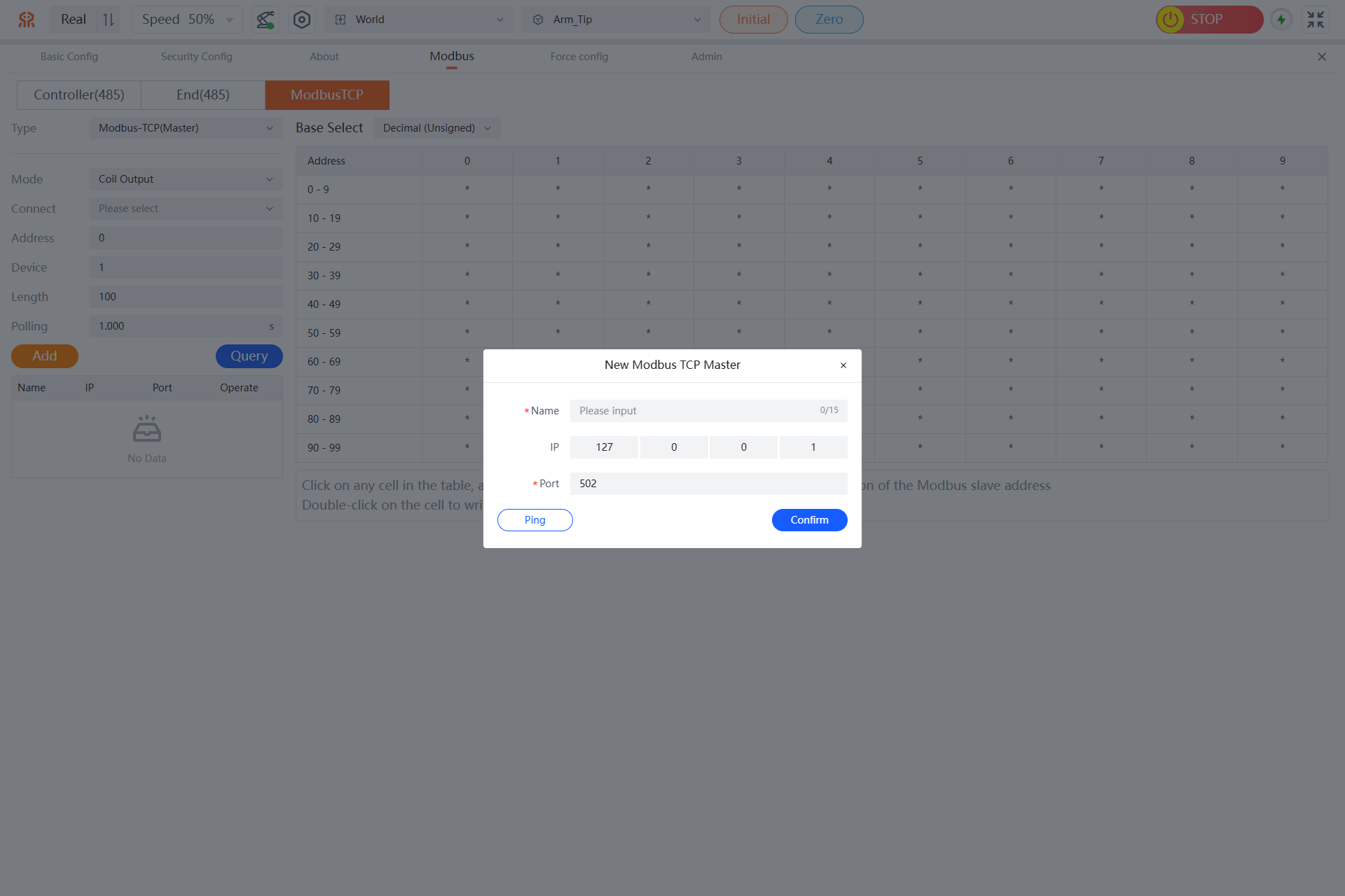
- After filling in the master name, IP, and port information, click
Confirmto add a new ModbusTCP master.
Once the master information is filled in, you can click thePingbutton to check the connectivity of the master address.
- After the ModbusTCP master is added, it can be viewed in the left list.
Ping
In the ModbusTCP master list on the ModbusTCP tab, click the Ping button in the operation column of the target master. If a prompt appears, it indicates that the connectivity test was successful; otherwise, it indicates a failure.
Edit
- In the ModbusTCP master list on the
ModbusTCPtab, click theEditbutton in the operation column of the target master to open the edit ModbusTCP master dialog box.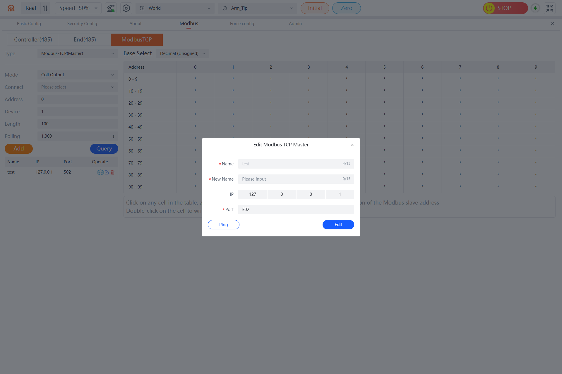
- Fill in the new name for the ModbusTCP master and modify the IP and port information as needed, then click
Editto complete the editing of the ModbusTCP master.
After modifying the master information, you can click thePingbutton to confirm the connectivity of the master address.
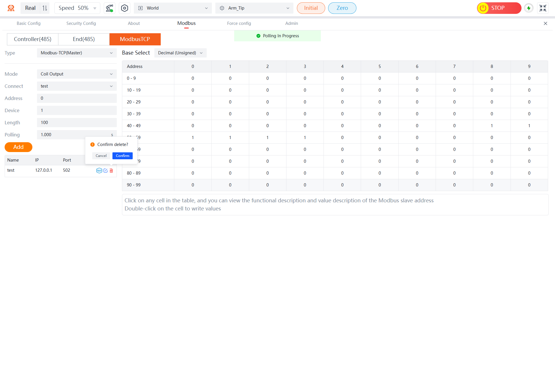
Delete
In the ModbusTCP master list on the ModbusTCP tab, click the Delete button in the operation column of the target master, and in the pop-up dialog box, click Confirm to complete the deletion of the ModbusTCP master.
Retrieve ModbusTCP Parameter Values
On the ModbusTCP tab, sequentially select the Modbus type, mode, and connect (only supported for Modbus-TCP master type), and set the address, device, length, and polling. Then click Query to retrieve the current data of the robotic arm. For specific address parameter values, refer to the Modbus Slave Address Table of the RM Robotic Arm.
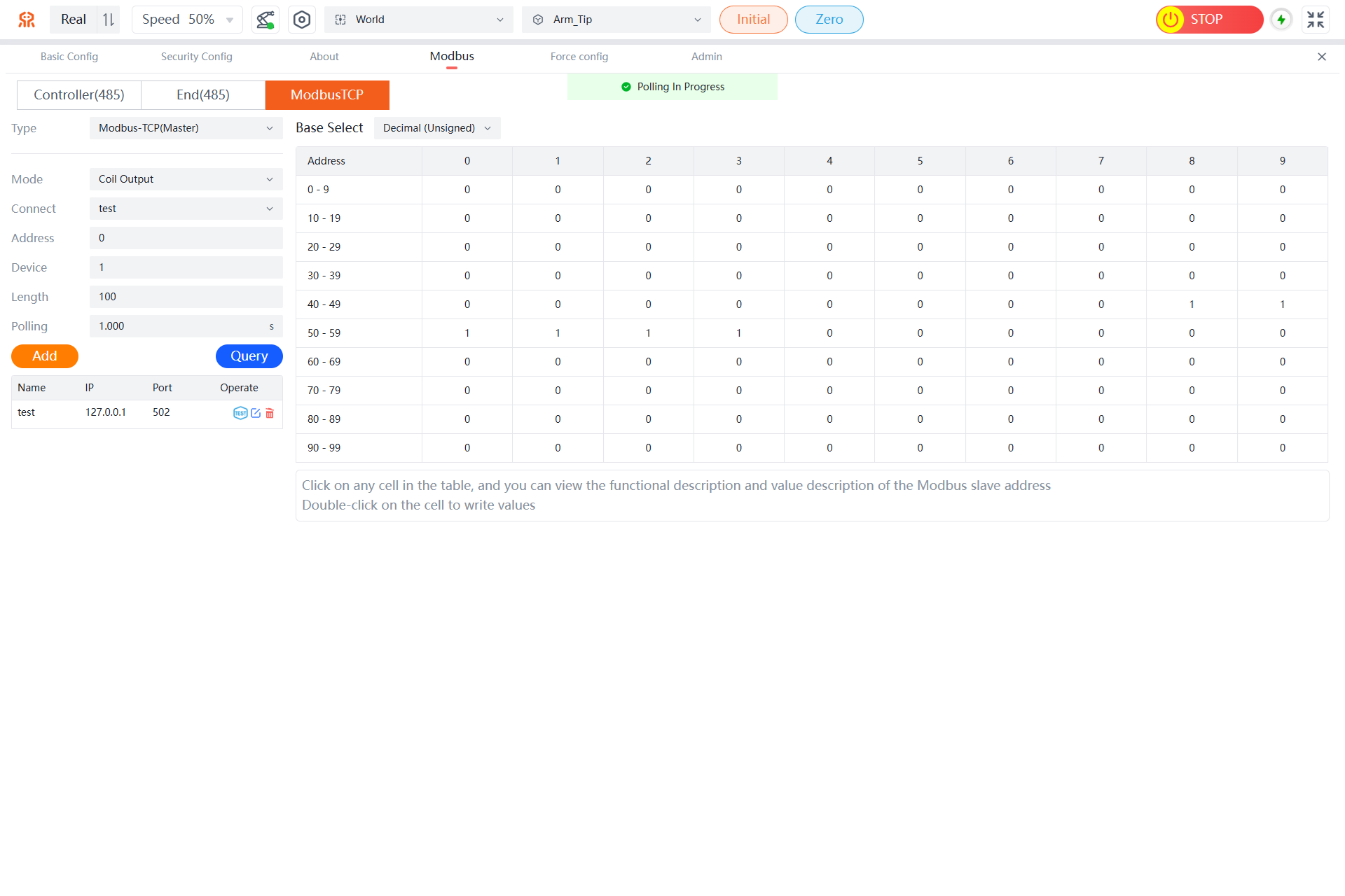
Note: Click any cell in the table to view the function and value description of the Modbus slave address; in the coil output and holding register models of the Modbus master station type, you can double-click a cell to write a value.
Modify ModbusTCP Parameter Values
- When the user selects the
Modbus-TCP(Master)type and chooses theCoil Outputmode, they can modify the parameter to 0 or 1 by double-clicking the corresponding address cell.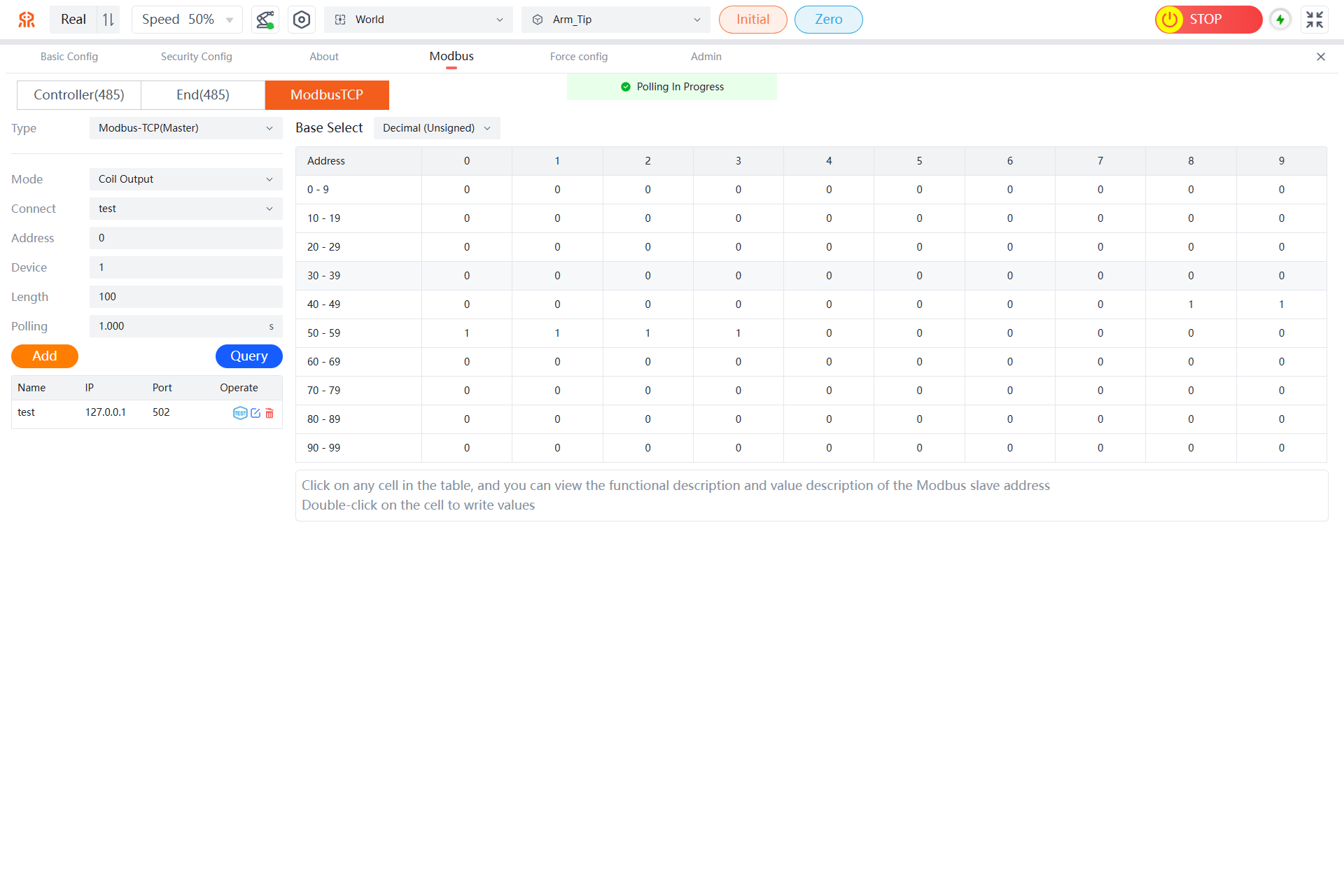
- When the user selects the
Modbus-TCP(Master)type and chooses theHolding Registermode, they can modify the parameter value of the corresponding cell by double-clicking it and entering a value in the data write dialog box that pops up. The length can be modified as needed to modify multiple address parameter values at once.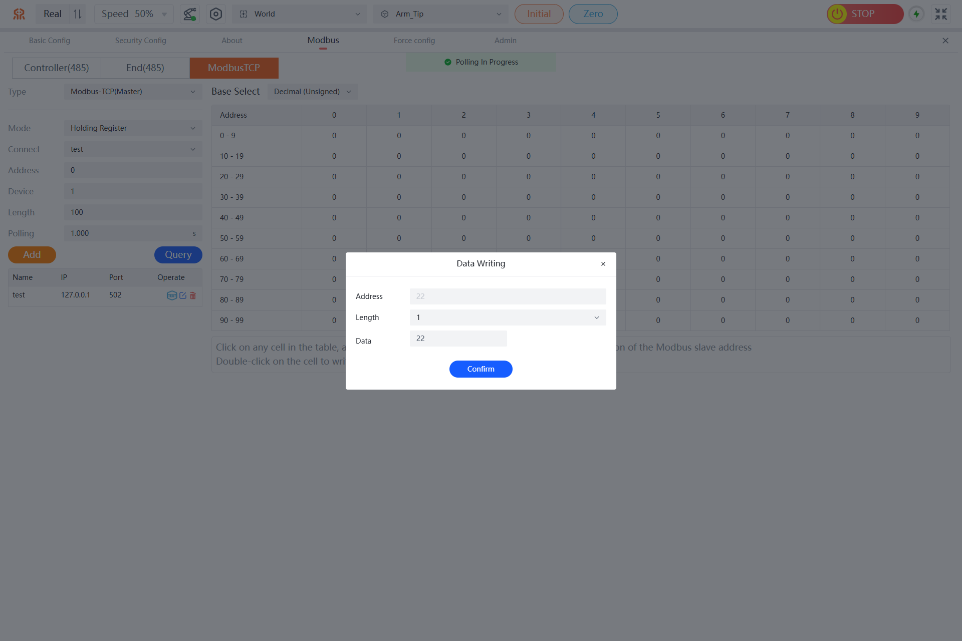
- For specific address parameter values, refer to the Modbus Slave Address Table of the RM Robotic Arm.
Force Config
The parameters of the 6-DoF Config are described in the following table:
| 6-DoF Config | ||||||
|---|---|---|---|---|---|---|
| Rated Load | X: 200N | Y: 200N | Z: 200N | MX: 7Nm | MY: 7Nm | MZ: 7Nm |
WARNING
The 6-DoF Config has a range of 200N/7Nm. If a force of more than 600N or a torque of more than 21Nm is applied to the end effector, it will cause irreversible damage to the sensor. During operation of the robotic arm, avoid hard collisions between the sensor and external devices to prevent damage.
The force config interface includes 6-DoF center of gravity calculation and sensor calibration.
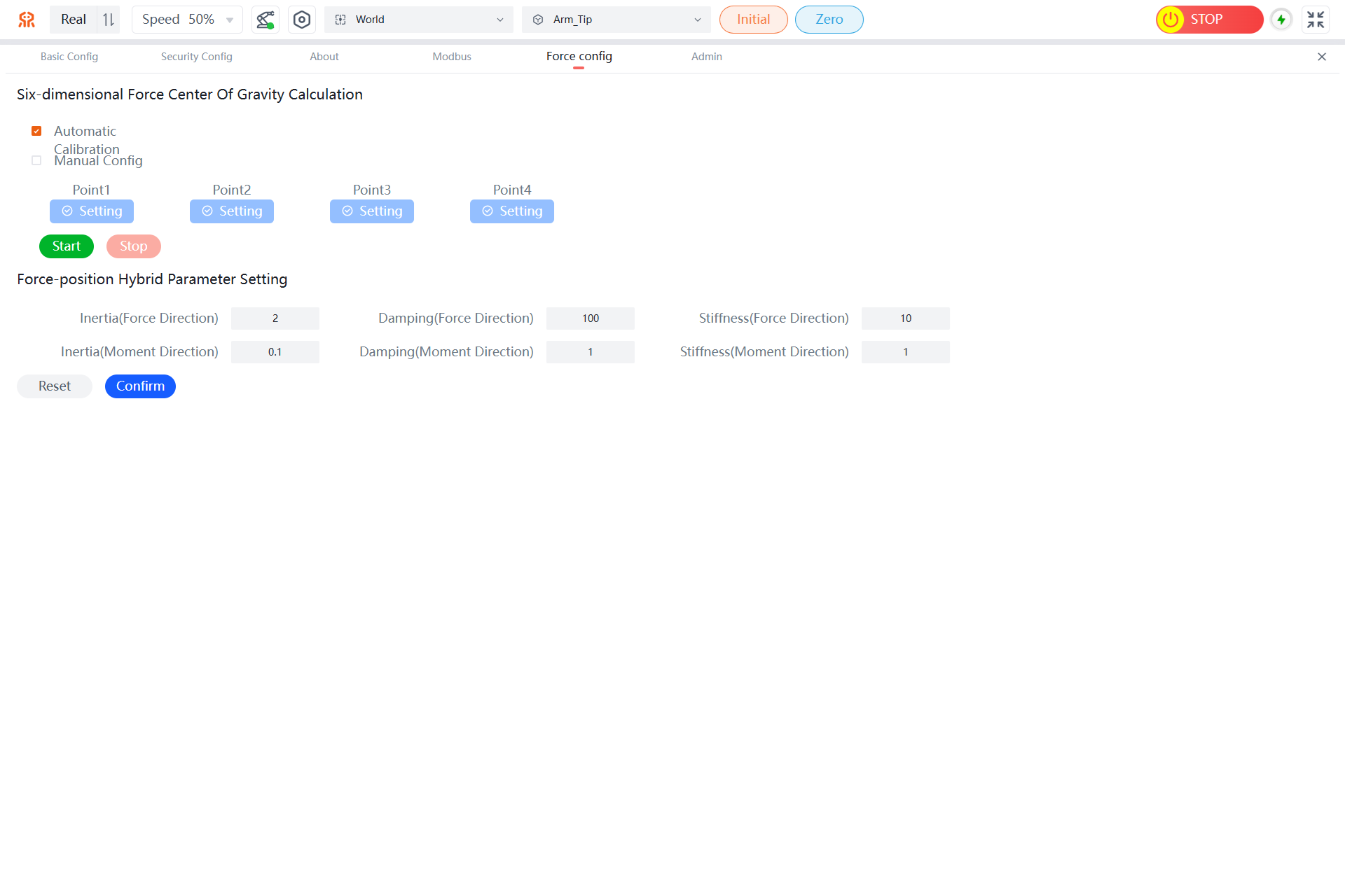
6-DoF Center of Gravity Calculation
The 6-DoF center of gravity calculation is required only when the end effector tool is changed. The calibration process can be performed automatically using pre-stored trajectory paths in the controller. To avoid interference with external devices during operation of the pre-stored trajectory, users can also perform manual calibration based on actual scenarios.
Automatic Calibration:
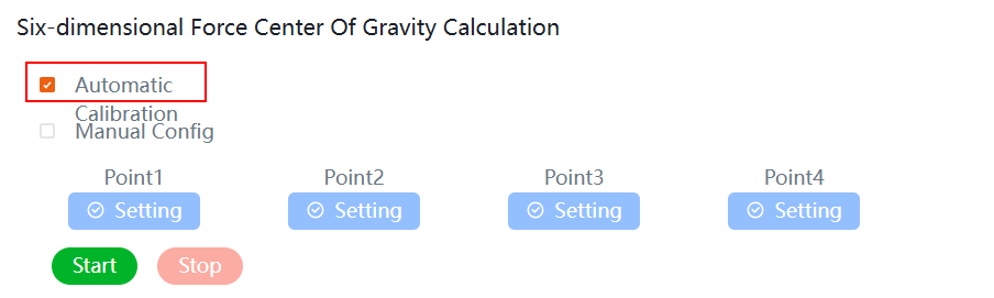
During automatic calibration, click the Start button to display a calibration status prompt as shown in the following figure.

The robot will automatically run through four predefined poses to calculate the center of gravity. If there is a risk of collision during movement, click the Stop button to terminate operation.
After successful 6-DoF center of gravity calibration, a "tip.calibrationsuccessful" prompt will appear, indicating that the center of gravity calibration is complete.

Manual Config:
During manual Config, check the Manual Config checkbox and use the robotic arm teaching interface to set four points with significantly different poses. After recording all four points, click the Confirm button.
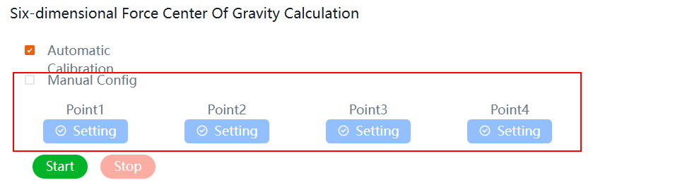
The robot automatically performs the 6-DoF center of gravity calculation. Once the "tip.calibrationsuccessful" prompt appears, the center of gravity calibration is complete.