
Ontology Parameters:
GEN62 Series Parameters and D-H Model Basic Parameters
| Parameter Name | Parameter Value | |
|---|---|---|
| Basic Parameters | Degrees of Freedom | 6 |
| Joint Brake Type | 1~6 joints with soft brakes | |
| Working Radius/mm | 660 | |
| Effective Rated Payload/kg | 2 | |
| Self-weight/kg | 3.5 | |
| Repeatability/mm | ±0.1 | |
| TCP Linear Speed/m/s | ≤2.5 | |
| Typical Power/W | ≤100 | |
| Peak Power/W | ≤180 | |
| Base Size/mm | φ88 | |
| Material | Aluminum alloy/ABS | |
| Environmental Adaptability | Operating Temperature/℃ | 0~45 |
| Operating Humidity | 25~85% no condensation | |
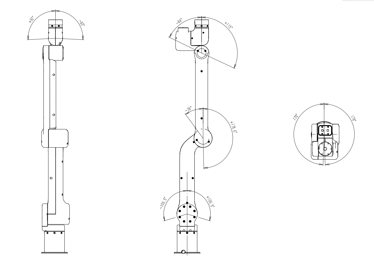
| Motion Range/° | J1 | -173~173 |
| J2 | -101~101 | |
| J3 | -31~173 | |
| J4 | -59~111 | |
| J5 | -88~88 | |
| J6 | -360~360 | |
| Maximum Angular Speed/°/s | J1 | 225 |
| J2 | 225 | |
| J3 | 225 | |
| J4 | 180 | |
| J5 | 180 | |
| J6 | 180 | |
Ontology Parameters
MDH model frame:
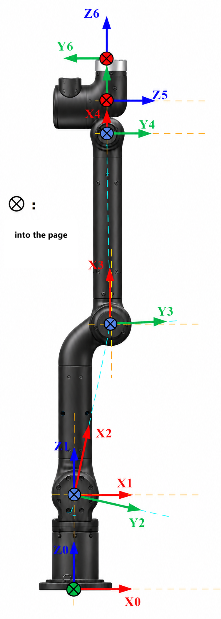
GEN62-B MDH parameters (modified D-H parameters):
| Joint No.(i) | Remarks | ||||
|---|---|---|---|---|---|
| 1 | 0 | 0 | 133.5 | 0 | |
| 2 | 0 | -90 | 3.5 | -78.09 | |
| 3 | 262.65 | 0 | 0 | -12.89 | |
| 4 | 290.04 | 0 | 0 | 0.98 | |
| 5 | 50 | -90 | 0 | -90 | |
| 6 | 0 | -90 | 63 | 0 | (B) Standard end effector |
Note: offset refers to the offset of the joint zero position from the model zero position, that is, model angle = joint angle + offset.
Kinetic parameters of the GEN62 robot link
| joint_id(i) | 1 | 2 | 3 | 4 | 5 | 6 |
|---|---|---|---|---|---|---|
| 0.158 | 1.606 | 0.351 | 0.484 | 0.23 | 0.063 | |
| -0.001 | 106.809 | 142.27 | 24.175 | -0.012 | 0.052 | |
| -21.715 | -5.367 | -2.007 | -28.658 | 13.448 | 0.331 | |
| -30.329 | 0.802 | -23.453 | -1.903 | -3.731 | -13.028 | |
| 396.698 | 1188.399 | 286.46 | 914.805 | 137.814 | 26.795 | |
| -0.007 | 1425.475 | 72.231 | 653.808 | 0.068 | 0.021 | |
| 0.001 | -294.733 | 1129.48 | 0.425 | 0.029 | 0.006 | |
| 301.568 | 41942.048 | 10627.596 | 710.788 | 73.471 | 26.722 | |
| -63.62 | 22.027 | -14.601 | -0.72 | 2.43 | 0.218 | |
| 223.59 | 42056.282 | 10445.817 | 1476.4 | 117.471 | 23.059 | |
| Remarks | Standard end effector |
Description:
is the mass of the link, is the x-coordinate of the center of mass of the link, is the y-coordinate of the center of mass of the link, is the z-coordinate of the center of mass of the link, , , , , , is the principal moment of inertia described in the link frame,
Remarks:
- Source of data: CAD design values.
- If the inertial parameters in the center of mass frame are required, they can be calculated based on the parallel axis theorem, as stated below.
Assuming there is an output frame
Where,
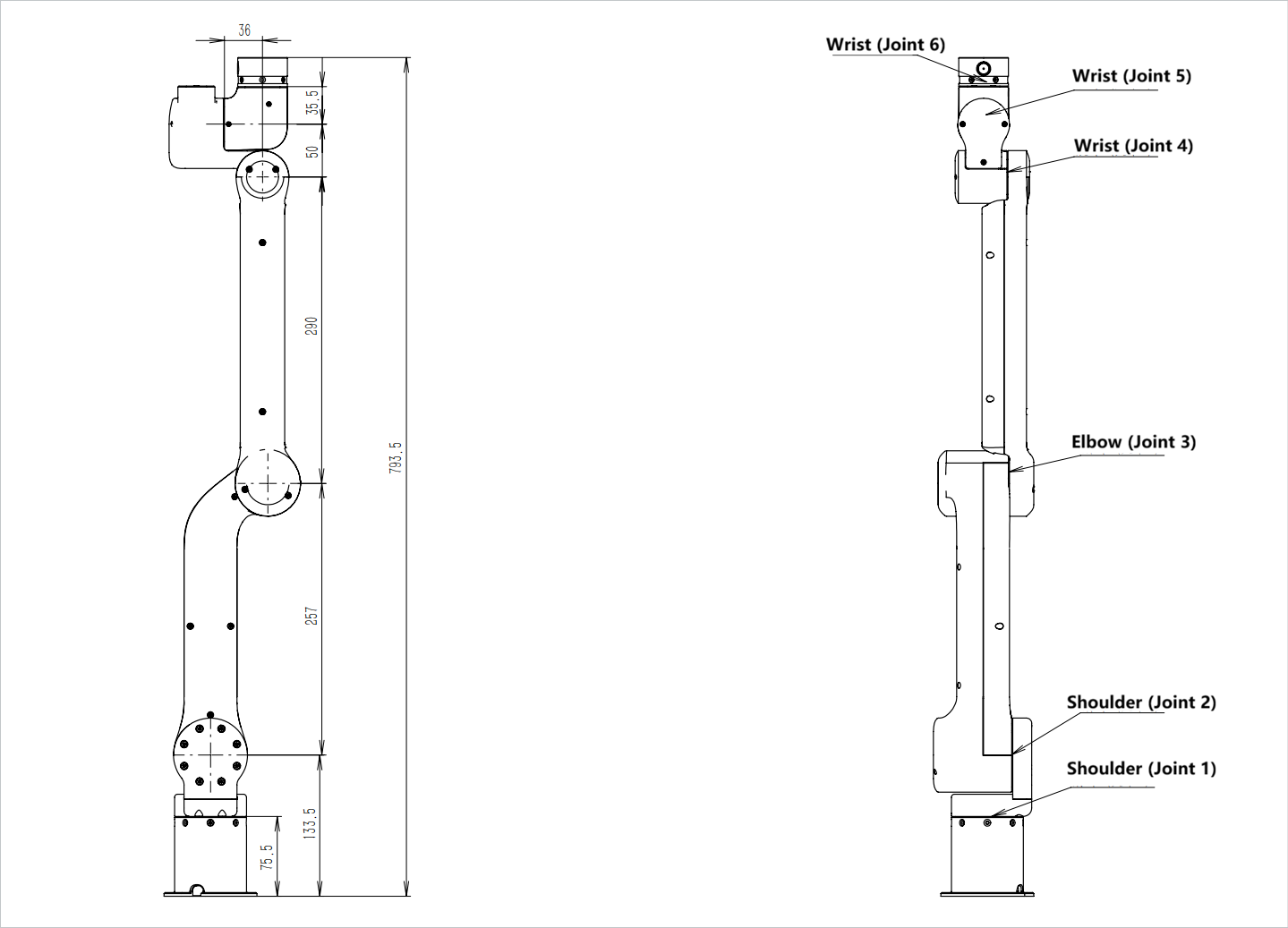
Distribution and dimensions of joints
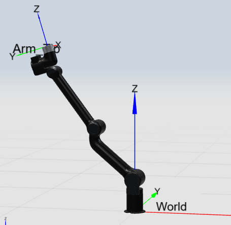
The GEN62 robot body has six rotating joints, each representing one degree of freedom. As shown in the figure below.
Working space
The GEN62 robot has the dual spatial characteristics of a large external envelope and a highly compact internal folding. The base (J1) has a rotation range of ±173°, and together with the continuous rotation of ±360° at the end (J6), it can achieve large-range omnidirectional posture adjustment. The core of its spatial characteristics lies in the large-span motion range of the elbow (J3), −31°∼173°, which enables it to have both a large extension radius and a very high inward folding capability, thereby effectively reducing the proximal interference blind zone. The overall working space balances extension and retraction, and is suitable for obstacle-avoidance operations and multi-posture operations in confined spaces.
The region with better manipulability is indicated by the yellow box in the figure below, and it forms an overall annular region in the working space.

Motion singularities
Singularity Type 1: Shoulder singularity
The shoulder singularity occurs when the wrist center point (i.e., the intersection of the axes of joint 5 and joint 6) lies on the axis of joint 1.
The shoulder singularity is as shown in the figure below. The blue plane in the figure is the plane that passes through the axis of joint 1 and is parallel to the axis of joint 2:
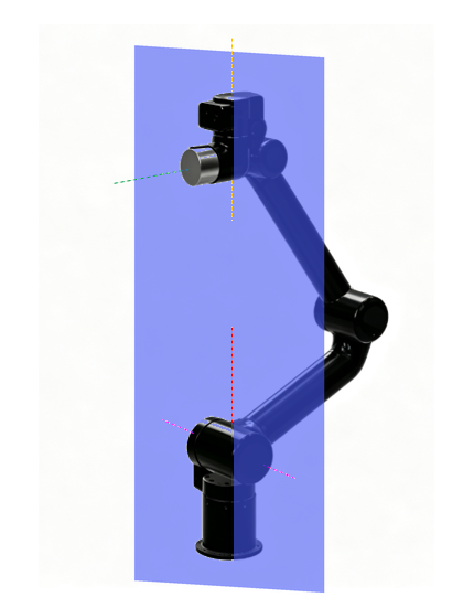
Representative point 1: [5.817, -53.625, 80.167, 63.4860, 5.817, 0.003], as shown in the figure below:
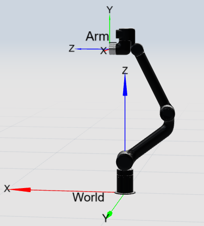
Singularity Type 2: Elbow singularity
The singularity occurs when q3=12.89°, that is, when the axes of joints 2, 3 and 4 are coplanar. The point format is [x,x,12.89,x,x,x]
Representative point 1: [0,40,12.89,-50,0,0], as shown in the figure below:
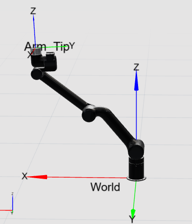
Singularity Type 3: Wrist singularity
The wrist singularity of the robotic arm occurs when q5=±90. The point format is [x,x,x,x,±90,x]
Representative point 1: [0,-20,100,0,90,0], as shown in the figure below:
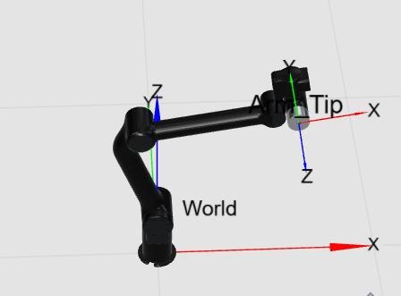
Singularity Type 4: Boundary singularity
When the end of the robotic arm reaches its farthest end, q3=12.89 and q5=0. The point format is [x,x,12.89,x,0,x]
Representative point 1: [0,-50,12.89,20,0,0], as shown in the figure below:
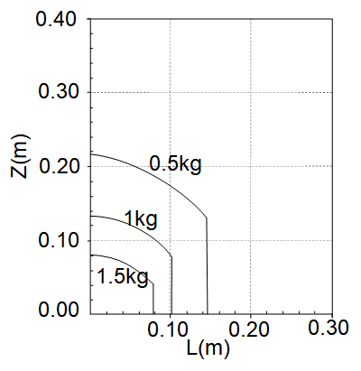
Payload curve
The figure below shows the payload curve of the end of the GEN62 robotic arm. L is the radial distance of the center of mass of the end payload relative to the end flange plane, and Z is the normal distance relative to the end flange plane.