Start guide:
Robotic Arm Teaching The teach pendant software panel is used for robot teaching operations. Users can move the robot by clicking on the icons on the panel. At the same time, the panel provides feedback on the robot's motion information to users.
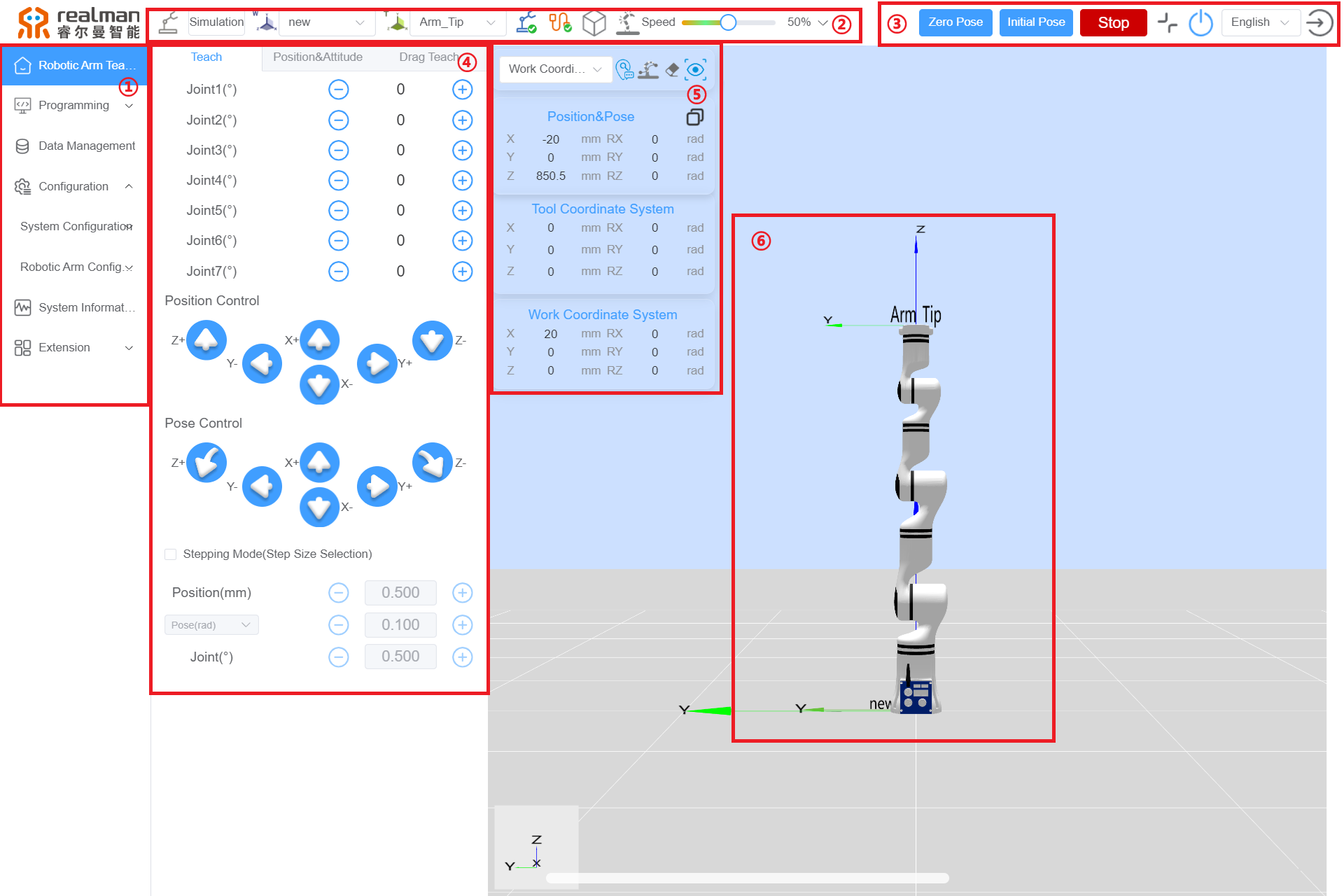
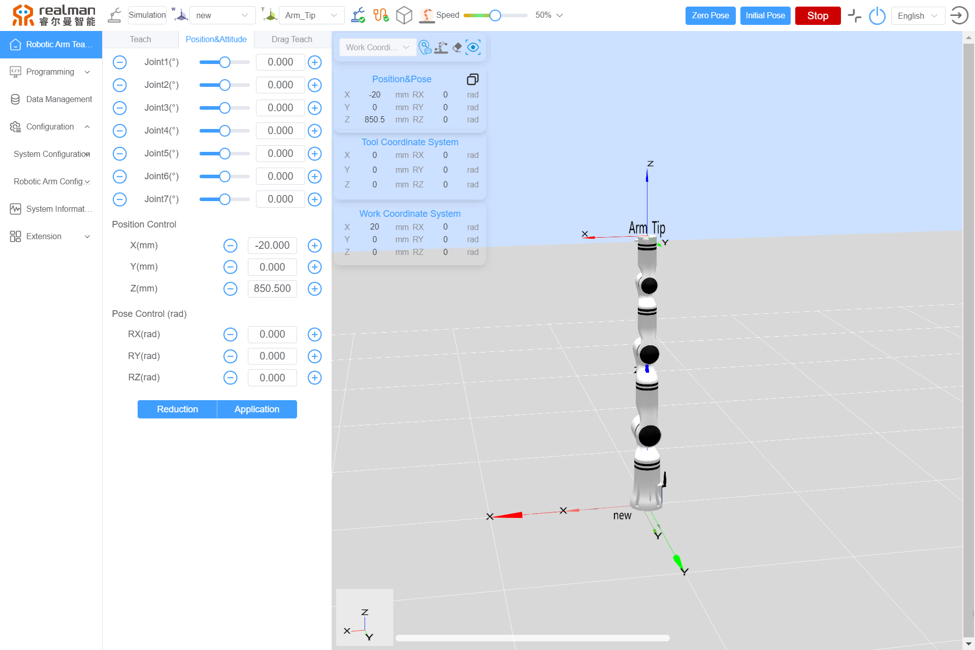
Names of functional areas on the robot teaching panel
| S/N | Name |
|---|---|
| 1 | Menu Bar Options: Including Robotic Arm Teach Pendant, Programming, Data Management, Configuration, System Information, and Extension. |
| 2 | Top Navigation Bar: Including Work Mode Selection, Work Coord Sys Selection, Tool Coord Sys Selection, Robotic Arm Status, Network, Electronic Fence, Collision Detection, and Teach Speed Percentage. |
| 3 | Quick Menu: Including Zero Pose, Initial Pose, Robot Emergency Stop/Recover, Full Screen/Exit Full Screen, Robot Power On/Off, Switch Language, and Log Out. |
| 4 | Teaching Area: Including Joint Teach, Position&Attitude Teach, Pose Teach, Step Mode Settings, Position Editing, and Drag Teach. |
| 5 | Work Coordinate System Area: Including Point Info, Draw Trajectories sfter open/close, Clear Trajectories, Reset perspective, Copy Joint Data, Copy Pose Data, Current Position&Pose, Tool Coordinate System, Work Coordinate System. |
| 6 | 3D Simulation Model: Including the 3D model of the robotic arm for simulation purposes. |
The following will explain each area/button in order according to the table above:
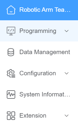
Menu bar options
Clicking on the menu bar options will switch to the corresponding panel, facilitating user operations. The selected panel is highlighted with a blue background.
Work mode selection
The yellow icon represents the selection of real mode, where the program runs on the actual robot. The robot moves according to the commands, and the interface displays the robot parameters and robotic arm motion state images.
The gray icon represents the selection of simulation mode, where the actual robot does not move, and only the 3D simulation model is operated. Before completing a robot program, users can first choose simulation mode to verify program feasibility. This improves the safety of robot applications and ensures the planned trajectory is reachable.

Work frame selection
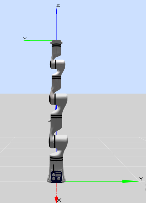
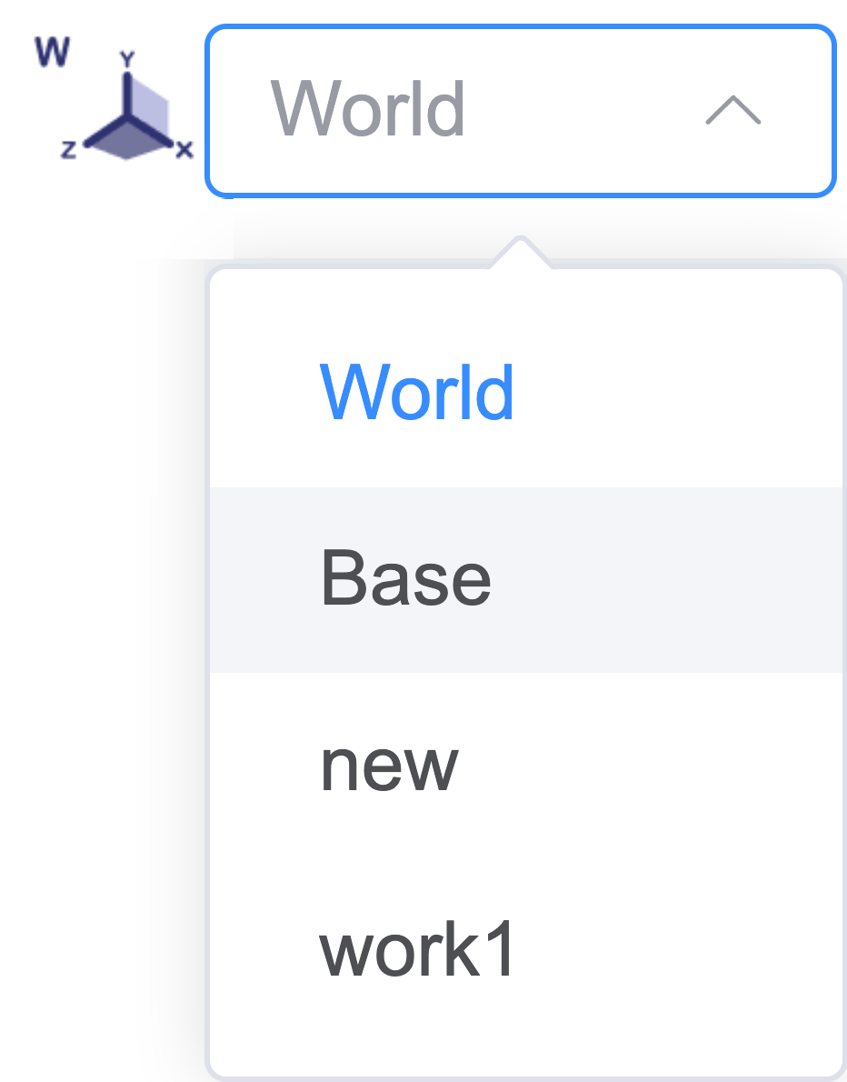
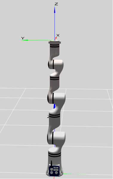
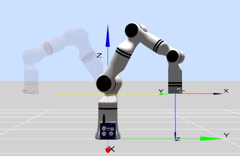
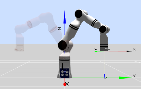
Users can select a work frame to control the robot's motion state. By choosing the base frame (Base) on the teach pendant interface, the robot will move in the direction of the frame as shown in the diagram. Users can also create a custom work frame based on actual project requirements to serve as a reference direction for robot movement. For example, work1 can be a user-defined work frame (method for setting the robot work frame). Once set, users can switch between work frames.
Tool frame selection
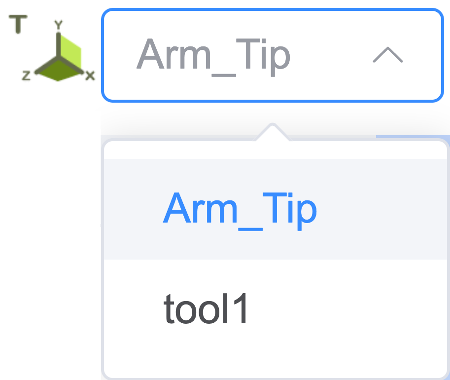
The tool frame can be selected from the drop-down menu. By default, the displayed pose target is the flange center. Users can set their own tool frame. For example, tool1 can be a user-defined tool frame (method for setting the robot tool frame). Once set, users can switch between tool frames.
Robotic arm state display
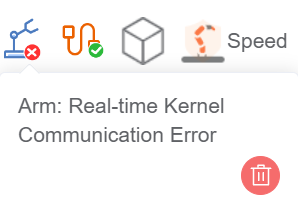
When an error occurs in the robot, it will be indicated here. Clicking the icon will open the error message list.
Network connection state display
When the connection to the robot is normal, it turns green; when communication is disconnected, it turns red.
Speed display
Here, you can either display in real-time or adjust the robot's movement speed as a percentage of its maximum speed using the slider.
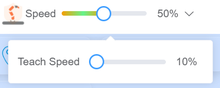
When using pose editing, this area can be used to set the data change speed when the '+' or '-' button is long-pressed.
Robot E-stop button
Pressing the E-stop button stops the robot at maximum speed. Pressing it again cancels the emergency stop, allowing the robotic arm to be operated again.

Full screen button
This button is used to control entering and exiting full-screen mode on the teaching interface.

Power button
This button is used to control the robot's power switch. Blue indicates that the robot power is on, and gray indicates that the robot power is off.

Switch Language
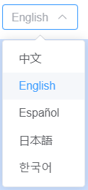
Click the language switch dropdown menu and select the target language to switch to it. Currently, it supports Chinese, English, Korean, Spanish, and Japanese.
Logout
Clicking the logout button logs the user out.
Joint control
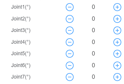
The robot has six degrees of freedom, with each joint named Joint 1 to Joint 6 from bottom to top, corresponding to the robot's six joints. Users can control the rotation of each robot joint using the joint control buttons on the teaching interface. "Increase" indicates increasing the joint angle, while "decrease" indicates decreasing the joint angle (unit: °).
Button table
| Increase | Decrease |
|---|---|
Position control
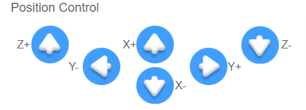
The end effector can perform position control based on the world frame (World), base frame (Base), end effector frame (Arm_Tip), and user-defined plane frames. Users can perform teaching for the end effector under different frames. For the X-axis, "negative direction" indicates movement in the negative direction of the X-axis, while "positive direction" indicates movement in the positive direction of the X-axis. Long press the button to move the robot, and release it to stop the movement. The same applies to the other axes.
Button table
| Negative direction | Positive direction |
|---|---|
 |  |
Orientation control
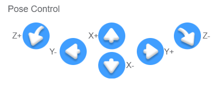
The end effector can perform orientation control based on the world frame (World), base frame (Base), end effector frame (Arm_Tip), and user-defined work and tool frames. Users can perform teaching for the end effector under different frames. During orientation teaching, the end position remains unchanged, while the orientation rotates around a specified coordinate axis. For RX, "negative direction rotation" indicates rotation around the X-axis in the negative direction, while "positive direction rotation" indicates rotation around the X-axis in the positive direction.
Button table
| Negative direction rotation | Positive direction rotation |
|---|---|
 |  |
Step mode setting
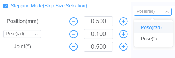
To improve teaching accuracy, the step control mode is used, allowing controlled variables to change accurately with step adjustments.
- First, check the "step mode" option box to activate step mode and enter step control.
- Users can adjust the step size of robot motion by clicking the buttons on either side of the step value.
- "Position": In the position control area, clicking a directional button moves the end effector a specified distance in the corresponding direction, with the unit in millimeters (The button must be held during movement, for releasing it will stop the robot midway).
- "Orientation": In the orientation control area, the angle of the end effector's orientation movement is set, with the unit in radians (rad) or degrees (°).
- "Joint": In the joint control area, the angle of the corresponding joint's movement is controlled, with the unit in degrees (°).
- Step control is only effective for end effector control and joint axis control.
Pose editing
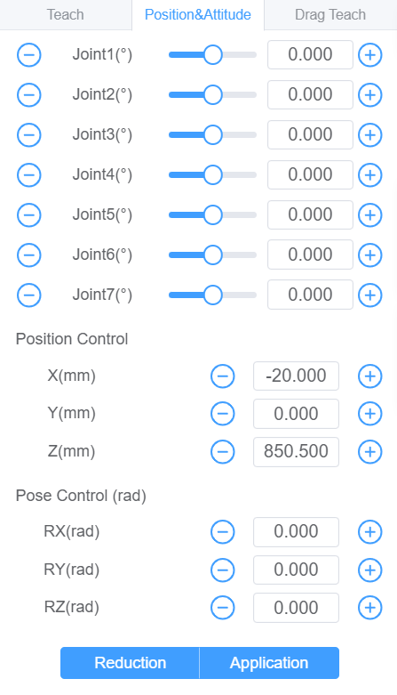
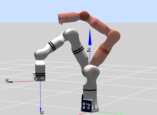
- By dragging the slider on the progress bar or moving the red virtual model's joints in the 3D simulation area, users can roughly adjust the joint angles of the robotic arm.
- The
+and-buttons can be used to fine-tune joint angles and position orientation, or parameters can be entered directly for adjustments. The adjusted position and orientation of the robotic arm are represented by the red virtual model. - Long press the
Applybutton to move the robotic arm to the position of the red virtual model; releasing the button stops the robotic arm. Clicking theResetbutton restores the red virtual model to match the real robotic arm's position.
Button table
| Progress bar slider | "+" and "-" buttons | "Apply" button | "Reset" button |
|---|---|---|---|
 |
Drag teaching
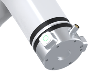
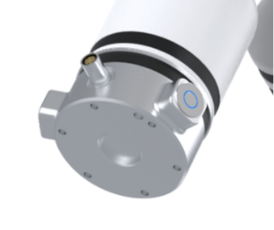
There are two buttons on the end flange housing of robotic arm, which are intended to control the drag teaching and trajectory replay respectively.
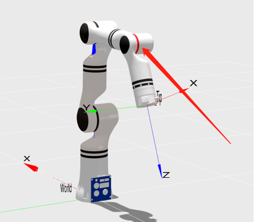
By pressing the green button at the end of robotic arm, the robotic arm will become draggable, and the trajectory will be recorded during the dragging process. Trajectory recording will be completed as long as the green button is released. The position of the end button is shown in the diagram.
By clicking the blue button at the end of the robotic arm, the robotic arm will automatically return to the starting position of the trajectory and replay the trajectory once (the robotic arm replays only the finally recorded drag trajectory).
Drag teaching trajectory trimming
The trajectories saved through drag teaching can be selected for execution or trimming here. Click the drop-down menu to select the trajectory to run, and then click the "Operation" button to execute it. During execution, you can click the "Stop" button to pause at any time. Once the execution is complete, click "Stop" again to manually stop the process.
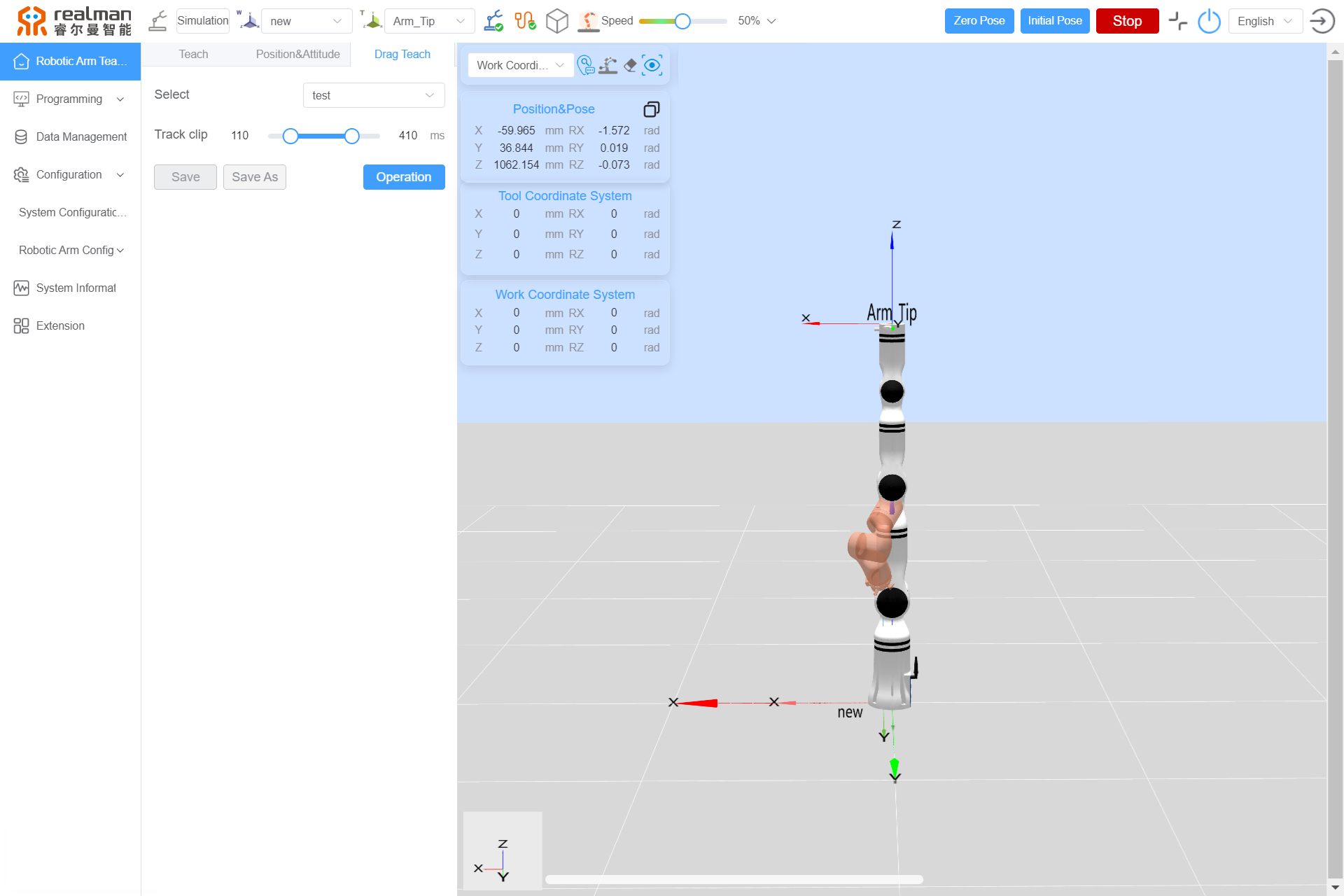
The sliders at both ends of the progress bar can be used to trim the trajectory. As shown in the figure below, when dragging the sliders, the red virtual robotic arm will display the pose of each point on the trajectory in real time, helping users determine the trim points. Once trimming is complete, click the "Save" button to overwrite the original trajectory, or click the "Save As" button to save the trimmed trajectory as a new trajectory.
Button table
| Drop-down menu | Run trajectory | Stop motion | Save | Save as |
|---|---|---|---|---|
Teaching frame selection
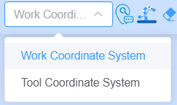
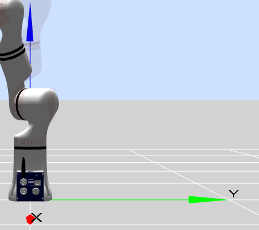
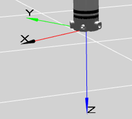
Select a frame to perform motion. When the tool frame is selected, the robot will move according to the direction of the tool frame.
Draw/clear trajectory
Enable the "Draw trajectory" function to display the real-time trajectory line of the end effector in the model preview area.
Enable the "Clear trajectory" function to remove the robot's trajectory line in the model preview area.
One-click return button
Click the "One-click return" button to quickly restore the 3D simulation model view to its initial view.
Zero orientation button
Zero orientation: long press the "Zero orientation" button to move the robot back to its zero position. Releasing the button stops the motion.
Initial orientation button
Initial position: long press the "Initial orientation" button to return the robot to its initial position. Users can customize the robot's initial position via the teach pendant interface (see the method for setting the initial position for details). Releasing the button stops the motion.
Robot position and orientation parameter display
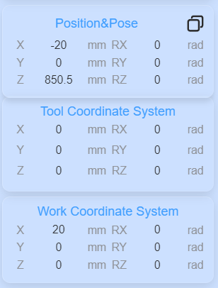
The X, Y, and Z values under position represent the coordinates of the tool flange center point (in the selected tool frame) within the selected frame (base frame, end frame, or user-defined frame). The RX, RY, and RZ values under orientation represent the rotation angles in radians relative to the selected frame.
Supports clicking the copy button in the upper right corner to choose between copying joint data or copying pose data, and then copying the corresponding data.
3D simulation model
The purpose of the robot simulation interface is to validate user-written programs without relying on the actual robotic arm. Users can verify the rationality of the robot's control program based on the simulation environment. Additionally, the model area includes the following user-friendly features:
- The simulation model can be resized and rotated by dragging the mouse (or touching the tablet interface) as needed.
- Each joint of the red virtual robotic arm can be dragged using the mouse. If the joint exceeds its limits, a pop-up warning will appear at the top of the page.
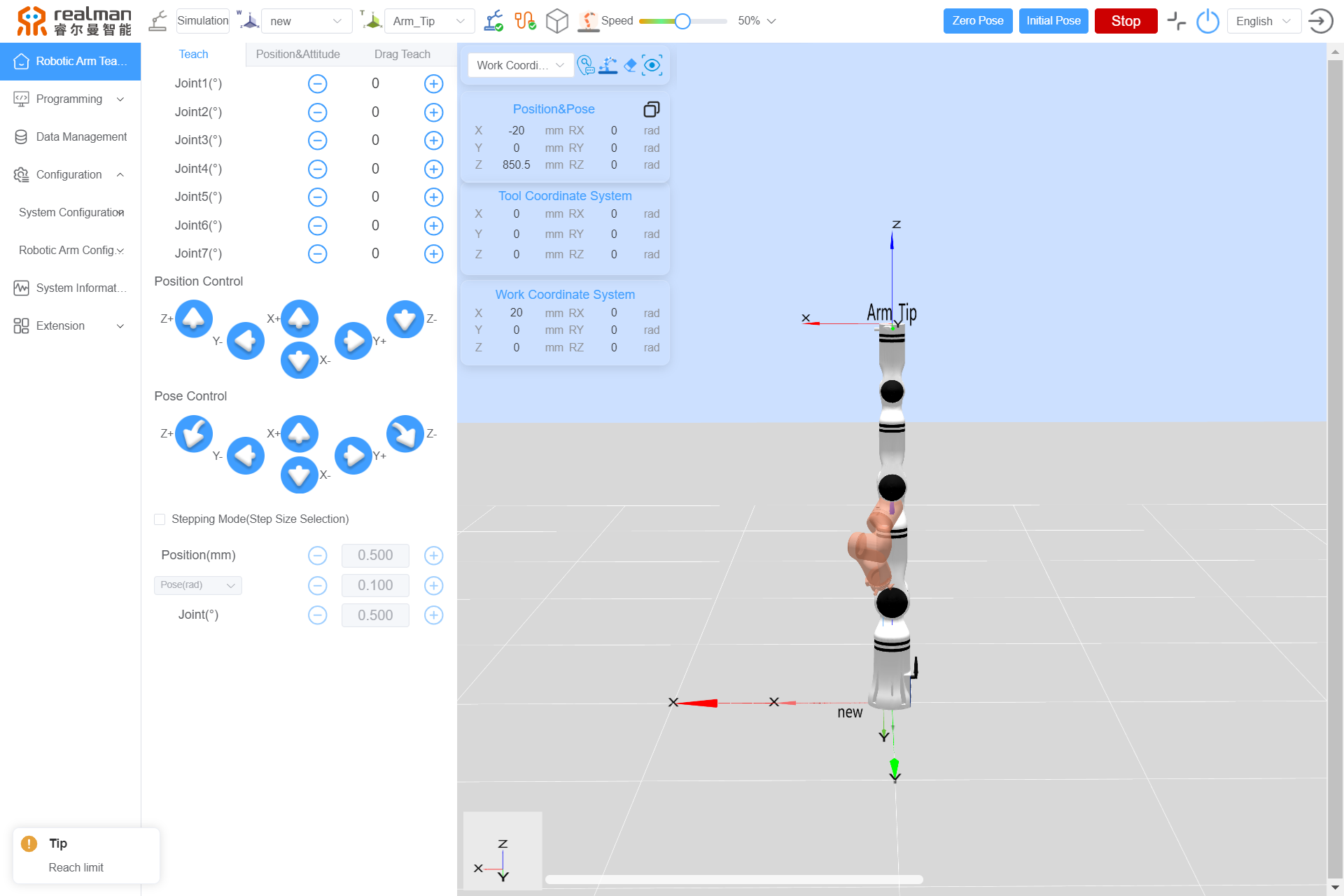
- If a joint reports an error, the corresponding joint in the model will turn red to alert the user.
