Demo (python):
ModbusRTU Demo 1. Project introduction
This project, via the RealMan Python development package, configures the ModbusRTU mode of the communication port, writes single coil data, reads single coil data, writes a single register, reads holding registers, and closes the communication port in ModbusRTU mode.
2. Code structure
RMDemo_ModbusRTU/
│
├── README.md        <- Core project document
├── requirements.txt    <- List of project dependencies
├── setup.py        <- Project installation script
│
├── src/          <- Project source code
│  ├── main.py       <- Main procedure entry
│  └── core/        <- Core function or business logic code
│└── demo_modbus_rtu.py<- Demo that configures the ModbusRTU mode of the communication port, writes single coil data, reads single coil data, writes a single register, reads holding registers, and closes the communication port in ModbusRTU mode.
└── Robotic_Arm/      <- RealMan robotic arm secondary development package
3. Project download
Download RM_API2 locally via the link: development package download. Then, navigate to the RM_API2\Demo\RMDemo_Python directory, where you will find RMDemo_ModbusRTU.
4. Environment configuration
Required environment and dependencies for running in Windows and Linux environments:
| Item | Linux | Windows |
|---|---|---|
| System architecture | x86 architecture | - |
| python | 3.9 or higher | 3.9 or higher |
| Specific dependency | - | - |
Linux configuration
Refer to the python official website - linux to download and install python3.9.
After entering the project directory, open the terminal and run the following command to install dependencies:
pip install -r requirements.txtWindows configuration
Refer to the python official website - Windows to download and install python3.9.
After entering the project directory, open the terminal and run the following command to install dependencies:
pip install -r requirements.txt5. Notes
This demo uses the RM65-B robotic arm as an example. Please modify the data in the code according to your actual situation.
6. User guide
6.1 Quick run
Follow these steps to quickly run the code:
Configuration of the IP address of the robotic arm: open the
demo_modbus_rtu.pyfile and modify the initialization parameters of theRobotArmControllerclass in themainfunction to the current IP address of the robotic arm. The default IP address is"192.168.1.18".python# Create a robot arm controller instance and connect to the robot arm robot_controller = RobotArmController("192.168.1.18", 8080, 3)Running via command line: navigate to the
RMDemo_ModbusRTUdirectory in the terminal and enter the following command to run the Python script:bashpython ./src/main.pyRunning result: Upon successful execution, the running state of the robotic arm will be displayed in the terminal.
After running the script, the output result is as follows:
current api version:  0.2.9

Successfully connected to the robot arm: 1

API Version:  0.2.9

Successfully set the Modbus mode

Successfully wrote the single coil

Successfully read the coils, data: [1]

Successfully wrote the single register

Successfully read the holding registers, data: [180]

Successfully closed the Modbus mode

Successfully disconnected from the robot arm
6.2 Code description
The following are the main functions of the demo_modbus_rtu.py file:
Connect the robotic arm
pythonrobot_controller = RobotArmController("192.168.1.18", 8080, 3)Connect the robotic arm to the specified IP address and port.
Get the API version
pythonprint("\nAPI Version: ", rm_api_version(), "\n")Get and display the API version.
Configure ModbusRTU mode.
pythonrobot_controller.set_modbus_mode()Write single coil data
pythonrobot_controller.write_single_coil(1)Read single coil data
pythonrobot_controller.read_coils()Write a single register
pythonrobot_controller.write_single_register(180)Read holding registers
pythonrobot_controller.read_holding_registers()Close ModbusRTU mode
pythonrobot_controller.close_modbus_mode()Disconnect from the robotic arm
pythonrobot_controller.disconnect()
7. License information
- This project is subject to the MIT license.
8. Controller and end effector interface diagram
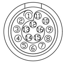
Controller IO Interface Diagram

The definitions of wires are explained in the following Table.
| No. | First-generation cable wiring sequence | Second-generation cable wiring sequence | Definition | Description | Wire number (for second-generation cables only) | Remarks |
|---|---|---|---|---|---|---|
| 1 | Pink and brown | Black stripe brown/brown | VOUT | External output + | NO.1 | 12 V/24 V |
| 2 | Gray and purple | Gray/purple | P_IO_GND | External output - | NO.2 | |
| 3 | Yellow | Yellow | 485A | NO.3 | ||
| 4 | Yellow and green | Black stripe yellow | 485B | NO.4 | ||
| 5 | Purple and white | Black stripe white | IO1 | Igital input/output bidirectional channel | NO.5 | |
| 6 | Red and white | White stripe red | IO2 | Igital input/output bidirectional channel | NO.6 | |
| 7 | Green and white | Black stripe green | IO3 | Igital input/output bidirectional channel | NO.7 | |
| 8 | Yellow and white | White stripe black | IO4 | Igital input/output bidirectional channel | NO.8 | |
| 9 | Blue and white | Black stripe orange | OUT_P_IN | Digital power supply for external input | NO.9 | 0−24 V |
| 10 | Light blue | Black stripe blue | OUT_P_OUT | Digital power supply for external output | NO.10 | 0−24 V |
| 11 | Deep blue | Blue | OUT_P_GND | External digital ground | NO.11 | |
| 12 | Green | Green | FDCAN_A | CAN_H | NO.12 | |
| 13 | Red | Red | FDCAN_B | CAN_L | NO.13 | |
| 14 | White | White | Blank | Reserved | NO.14 | |
| 15 | Black | Black | Blank | Reserved | NO.15 | |
| 16 | Orange | Orange | Blank | Reserved | NO.16 |
Note
The voltage of digital I/O is determined based on the reference voltage connected, and the 16-core extension interface cable of robotic arm provides only 12 V and 24 V power supply voltages. If other output voltages are required for the digital I/O, then reference voltages need to be led in from the pins OUT_P_OUT+, OUT_P_IN+, and OUT_P_GND.
End Effector IO Interface Diagram
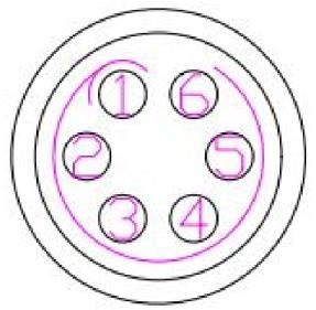
The end effector IO interface connects external tools through a 6-core aerial plug. The pins and definitions of the aerial plug are as follows.

| Pin No. | Wiring color | Function |
|---|---|---|
| 1 | Yellow | RS485_A |
| 2 | White | RS485_B |
| 3 | Red | Digital interface 1 (DI1/DO1) |
| 4 | Black | Digital interface 2 (DI2/DO2) |
| 5 | Green | Power GND |
| 6 | Blue | Power output: 0 V/12 V/24 V, controllable by program |
Note
The multiplexing functions in the table above are switched by program commands. Pin 3 and pin 4 are digital input channels (DI1 and DI2) by default before delivery, and the power output of pin 6 is 0 V (programmed).

